Nissan Murano Z51. Manual - part 1409


  Главная      Nissan     Nissan Murano Z51 (2010 year) - Service Manual


поиск по сайту            


содержание   ..  1407  1408  1409  1410   ..


Nissan Murano Z51. Manual - part 1409


STR-6

< SYSTEM DESCRIPTION >

STARTING SYSTEM

Component Description

INFOID:0000000005517074
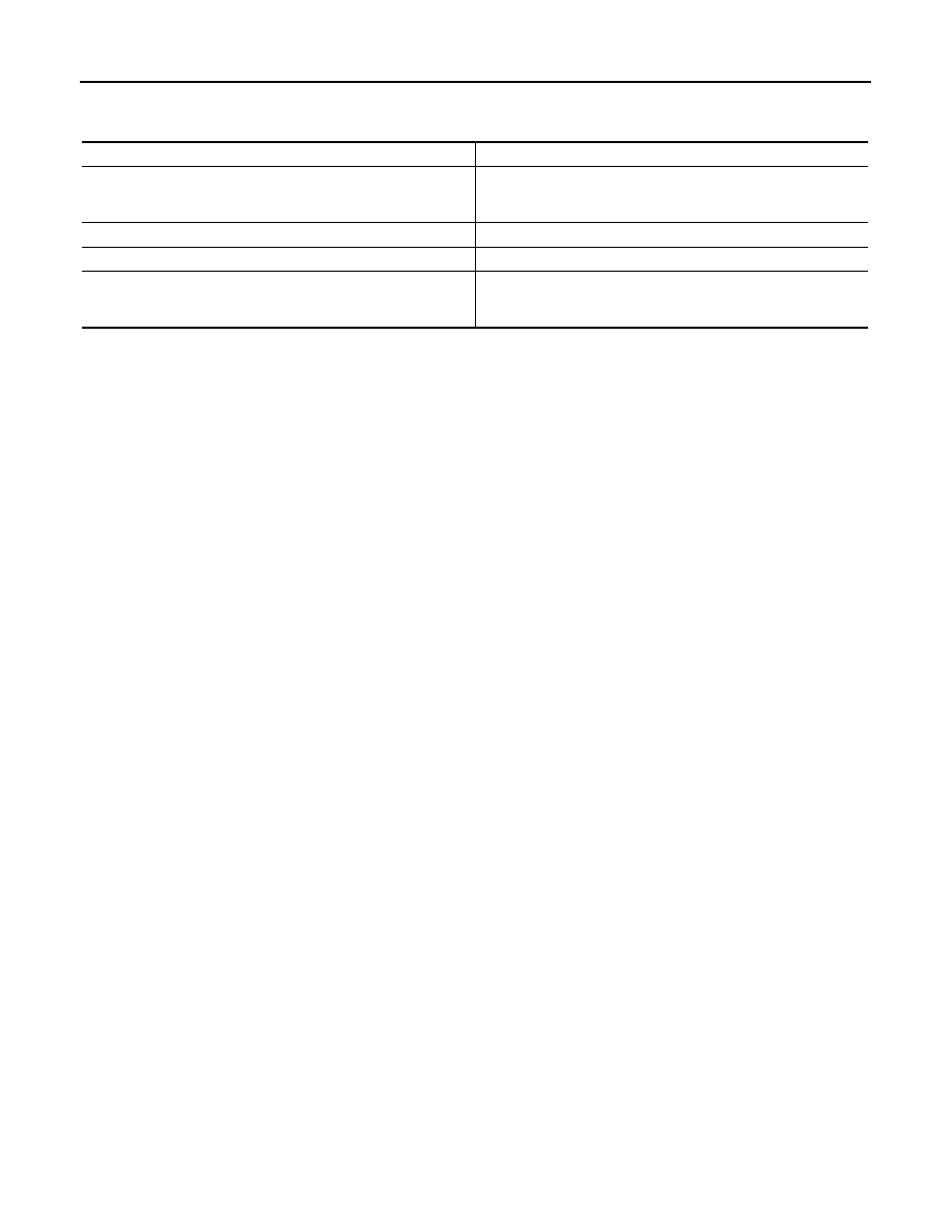
Component part

Description

TCM

TCM supplies power to the starter relay and starter control relay 
inside IPDM E/R when the selector lever is shifted to the P or N 
position.

BCM

BCM controls the starter relay inside IPDM E/R.

IPDM E/R

CPU inside IPDM E/R controls the starter control relay.

Starter motor

The starter motor plunger closes and the motor is supplied with 
battery power, which in turn cranks the engine, when the “S” ter-
minal is supplied with electric power.

B TERMINAL CIRCUIT

STR-7

< DTC/CIRCUIT DIAGNOSIS >

C

D

E

F

G

H

I

J

K

L

M

A

STR

N

P

O

DTC/CIRCUIT DIAGNOSIS

B TERMINAL CIRCUIT

Description

INFOID:0000000005517075

The “B” terminal is constantly supplied with battery power.

Diagnosis Procedure

INFOID:0000000005517076

CAUTION:

Perform diagnosis under the condition that engine cannot start by the following procedure.
1.

Remove fuel pump fuse.

2.

Crank or start the engine (where possible) until the fuel pressure is released.

1.

CHECK “B” TERMINAL CIRCUIT

1.

Turn ignition switch OFF.

2.

Check that starter motor “B” terminal connection is clean and tight.

3.

Check voltage between starter motor “B” terminal and ground.

Is the inspection result normal?

YES

>> GO TO 2.

NO

>> Check harness between battery and starter motor for open circuit.

2.

CHECK BATTERY CABLE CONNECTION STATUS (VOLTAGE DROP TEST)

1.

Shift the selector lever to “P” or “N” position.

2.

Check voltage between battery positive terminal and starter motor “B” terminal.

Is the inspection result normal?

YES

>> GO TO 3.

NO

>> Check harness between the battery and the starter motor for poor continuity.

3.

CHECK GROUND CIRCUIT STATUS (VOLTAGE DROP TEST)

1.

Shift the selector lever to “P” or “N” position.

2.

Check voltage between starter motor case and battery negative terminal.

Is the inspection result normal?

YES

>> “B” terminal circuit is OK. Further inspection is necessary. Refer to 

STR-2, "Work Flow"

.

NO

>> Check the starter motor case and ground for poor continuity.

Terminals

Voltage (Approx.)

(+)

(–)

Starter motor “B” terminal

Terminal

F10

2 Ground

Battery 

voltage

Terminals

Condition

Voltage (Approx.)

(+)

(–)

Starter motor

“B” terminal

Terminal

Battery positive terminal

F10

When the ignition switch is 

in START position

Less than 

 0.5 V

Terminals

Condition

Voltage (Approx.)

(+)

(–)

Starter motor case

Battery negative terminal

When the ignition switch is in 

START position

Less than 0.2 V

STR-8

< DTC/CIRCUIT DIAGNOSIS >

S CONNECTOR CIRCUIT

S CONNECTOR CIRCUIT

Description

INFOID:0000000005517077

The starter motor magnetic switch is supplied with power when the ignition switch is turned to the START posi-
tion while the selector lever is in the P or N position.

Diagnosis Procedure

INFOID:0000000005517078

CAUTION:

Perform diagnosis under the condition that engine cannot start by the following procedure.
1.

Remove fuel pump fuse.

2.

Crank or start the engine (where possible) until the fuel pressure is released.

1.

CHECK “S” CONNECTOR CIRCUIT

1.

Turn ignition switch OFF.

2.

Disconnect starter motor connector.

3.

Shift the selector lever to “P” or “N” position.

4.

Check voltage between starter motor harness connector and ground.

Is the inspection result normal?

YES

>> “S” connector circuit is OK. Further inspection is necessary. Refer to 

STR-2, "Work Flow"

.

NO

>> GO TO 2.

2.

CHECK HARNESS CONTINUITY (OPEN CIRCUIT)

1.

Disconnect IPDM E/R connector.

2.

Check continuity between starter motor harness connector and IPDM E/R harness connector.

Is the inspection result normal?

YES

>> Further inspection is necessary. Refer to 

SEC-5, "Work Flow"

 in SEC section. 

NO

>> Repair the harness.

Terminals

Condition

Voltage (Approx.)

(+)

(–)

Starter motor har-

ness connector

Terminal

F47

1 Ground

When the ignition switch is in 

START position

Battery voltage

Starter motor harness connector

IPDM E/R harness connector

Continuity

Connector No.

Terminal No.

Connector No.

Terminal No.

F47

1

F12

80

Existed

STARTING SYSTEM

STR-9

< DTC/CIRCUIT DIAGNOSIS >

C

D

E

F

G

H

I

J

K

L

M

A

STR

N

P

O

STARTING SYSTEM

Wiring Diagram - STARTING SYSTEM -

INFOID:0000000005517079

JCBWM1068GB


содержание   ..  1407  1408  1409  1410   ..