содержание .. 124 125 126 127 ..
Nissan Murano Z51. Manual - part 126
AV
REAR DISPLAY UNIT
AV-283
< ECU DIAGNOSIS INFORMATION >
[BOSE AUDIO WITHOUT NAVIGATION]
C
D
E
F
G
H
I
J
K
L
M
B
A
O
P
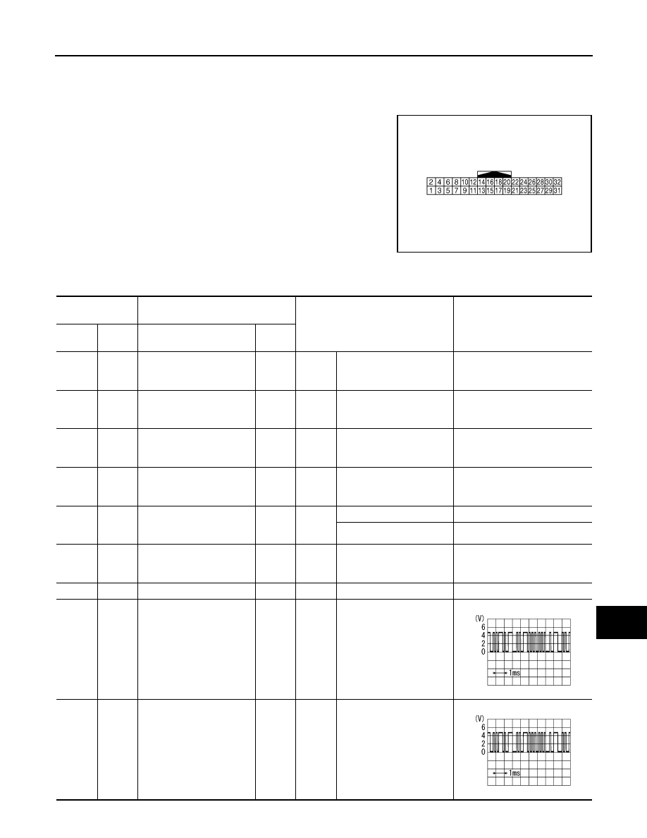
REAR DISPLAY UNIT
Reference Values
INFOID:0000000005528589
TERMINAL LAYOUT
PHYSICAL VALUES
JSNIA1147ZZ
Terminal
(Wire color)
Description
Condition
Reference value
(Approx.)
+
–
Signal name
Input/
Output
1
(B)
Ground
Ground
—
Ignition
switch
ON
—
0 V
2
(B)
Ground
Ground
—
Ignition
switch
ON
—
0 V
3
(Y/R)
Ground
Battery power supply
Input
Ignition
switch
ON
—
Battery voltage
4
(Y/R)
Ground
Battery power supply
Input
Ignition
switch
ON
—
Battery voltage
5
(R)
Ground
Headphone amp. ON sig-
nal
Input
Ignition
switch
ON
Headphone mode is ON.
4.5 V
Headphone mode is OFF.
0 V
6
(V/Y)
Ground
ACC power supply
Input
Ignition
switch
ACC
—
Battery voltage
8
—
Shield
—
—
—
—
9
(V)
Ground
Communication signal
(DISP
→
DIST)
Output
Ignition
switch
ON
Rear seat remote controller
operation when AUX or
DVD image is displayed on
rear displayed.
10
(LG)
Ground
Communication signal
(DIST
→
DISP)
Input
Ignition
switch
ON
Rear seat remote controller
operation when AUX or
DVD image is displayed on
rear displayed.
PKIB5039J
PKIB5039J