содержание .. 1196 1197 1198 1199 ..
Nissan Murano Z51. Manual - part 1198
RSU-16
< REMOVAL AND INSTALLATION >
REAR SUSPENSION ARM
REAR SUSPENSION ARM
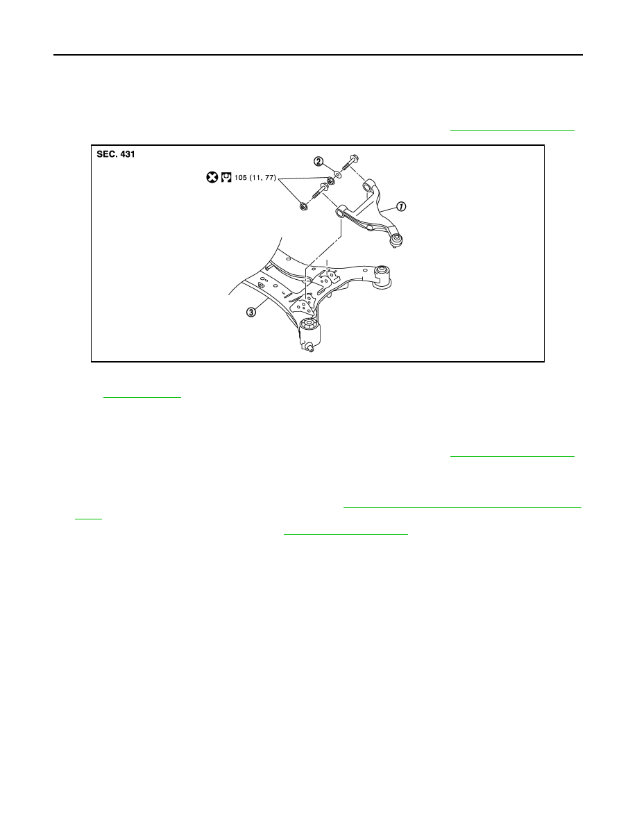
Exploded View
INFOID:0000000005514363
NOTE:
Remove suspension arm with rear suspension member for AWD models. Refer to
.
Removal and Installation
INFOID:0000000005514364
NOTE:
Remove suspension arm with rear suspension member for AWD models. Refer to
.
REMOVAL
1.
Remove tire with power tool.
2.
Remove wheel sensor and sensor harness. Refer to
BRC-111, "REAR WHEEL SENSOR : Exploded
.
3.
Remove stabilizer connecting rod. Refer to
.
4.
Remove cotter pin of suspension arm ball joint, and loosen nut.
5.
Use the ball joint remover to remove suspension arm from axle housing. Be careful not to damage ball
joint boot.
CAUTION:
Tighten temporarily mounting nut to prevent damage to threads and to prevent ball joint remover
from coming off.
6.
Remove suspension arm.
INSTALLATION
Note the following, and install in the reverse order of removal.
• Perform final tightening of rear suspension member installation position (rubber bushing), under unladen
conditions with tires on level ground.
Inspection
INFOID:0000000005514365
INSPECTION AFTER REMOVAL
Appearance
Check the following items, and replace the part if necessary.
• Suspension arm and bushing for deformation, cracks or damage.
• Boot of ball joint for cracks or damage, and also for grease leakage.
1.
Suspension arm
2.
Stopper rubber
3.
Rear suspension member
Refer to
for symbols in the figure.
JPEIB0141GB