содержание .. 1166 1167 1168 1169 ..
Nissan Murano Z51. Manual - part 1168
RF-12
< DTC/CIRCUIT DIAGNOSIS >
POWER SUPPLY AND GROUND CIRCUIT
Is the inspection result normal?
YES
>> GO TO 3.
NO
>> GO TO 2.
2.
CHECK SUNROOF MOTOR CIRCUIT
1.
Turn ignition switch OFF.
2.
Disconnect BCM connector.
3.
Check continuity between BCM harness connector and sunroof motor assembly harness connector.
4.
Check continuity between BCM harness connector and ground.
Is the inspection result normal?
YES
>> Refer to
BCS-95, "Removal and Installation"
.
NO
>> Repair or replace harness.
3.
CHECK GROUND CIRCUIT
1.
Turn ignition switch OFF.
2.
Check continuity between sunroof motor assembly harness connector and ground.
Is the inspection result normal?
YES
>> GO TO 4.
NO
>> Repair or replace harness.
4.
CHECK INTERMITTENT INCIDENT
GI-39, "Intermittent Incident"
>> INSPECTION END
SUNSHADE MOTOR ASSEMBLY
SUNSHADE MOTOR ASSEMBLY : Diagnosis Procedure
INFOID:0000000005516832
1.
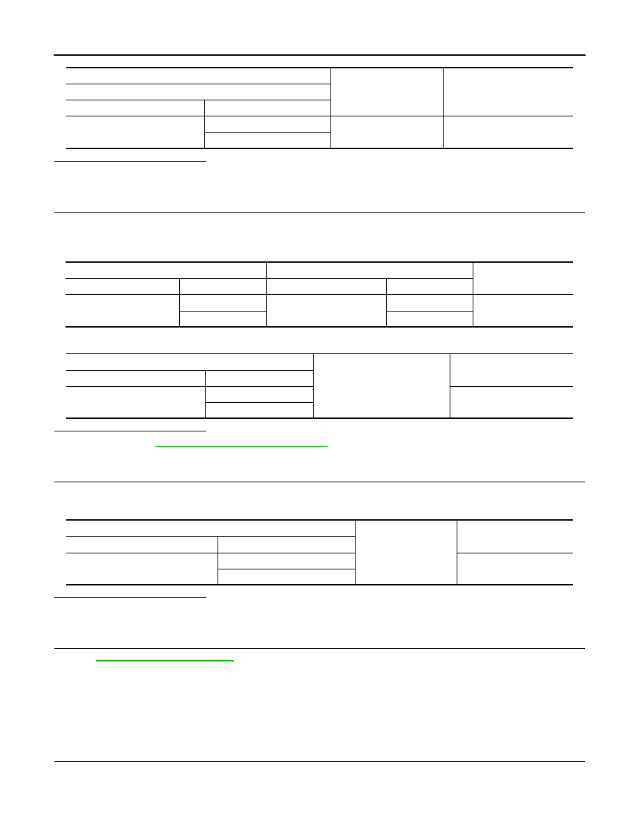
CHECK POWER SUPPLY
1.
Turn ignition switch OFF.
2.
Disconnect sunshade motor assembly connector.
3.
Turn ignition switch ON.
(+)
(–)
Voltage (V)
(Approx.)
Sunroof motor assembly
Connector
Terminal
R101
3
Ground
Battery voltage
6
BCM
Sunroof motor assembly
Continuity
Connector
Terminal
Connector
Terminal
M118
2
R101
6
Existed
3
3
BCM
Ground
Continuity
Connector
Terminal
M118
2
Not existed
3
Sunroof motor assembly
Ground
Continuity
Connector
Terminal
R101
1
Existed
2