содержание .. 1162 1163 1164 1165 ..
Nissan Murano Z51. Manual - part 1164
RAX-18
< REMOVAL AND INSTALLATION >
[AWD]
REAR DRIVE SHAFT
ii.
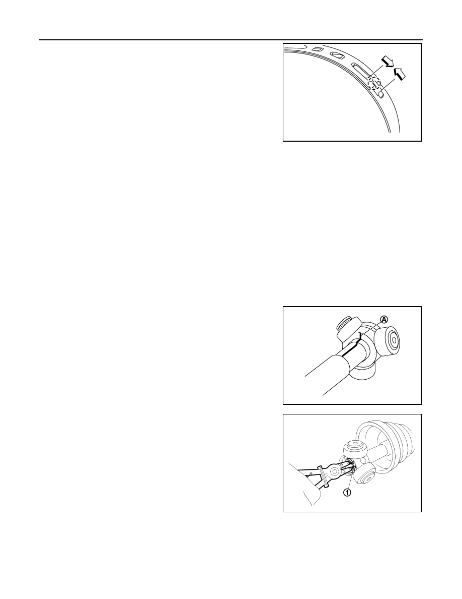
Pinch projection on the band with suitable pliers to tighten band.
iii.
Insert tip of band below end of the pawl.
11. Secure joint sub-assembly and shaft, and then make sure that they are in the correct position when rotat-
ing boot. Install them with boot band when the mounting positions become incorrect.
CAUTION:
Never reuse boot band.
FINAL DRIVE SIDE
FINAL DRIVE SIDE : Disassembly and Assembly
INFOID:0000000005514299
DISASSEMBLY
1.
Fix shaft with a vise.
CAUTION:
Protect shaft when fixing with a vise using aluminum or copper plates.
2.
Remove boot bands, and then remove boot from housing.
3.
Put matching marks on housing and shaft, and then pull out housing from shaft.
CAUTION:
Use paint or an equivalent for matching marks. Never scratch the surface.
4.
Put matching marks (A) on the spider assembly and shaft.
CAUTION:
Use paint or an equivalent for matching marks. Never
scratch the surface.
5.
Remove snap ring (1), and then remove spider assembly from
shaft.
6.
Remove boot from shaft.
7.
Remove circular clip housing.
8.
Remove dust shield to housing.
9.
Remove old grease on housing with paper waste.
ASSEMBLY
1.
Install boot and boot band to shaft.
CAUTION:
• Wrap serration on shaft with tape to protect boot from damage.
• Never reuse boot and boot band.
2.
Remove the tape wrapped around the serration on shaft.
JPDIF0158ZZ
JPDIF0006ZZ
JPDIF0014ZZ