содержание .. 1070 1071 1072 1073 ..
Nissan Murano Z51. Manual - part 1072
PCS-30
< ECU DIAGNOSIS INFORMATION >
[IPDM E/R]
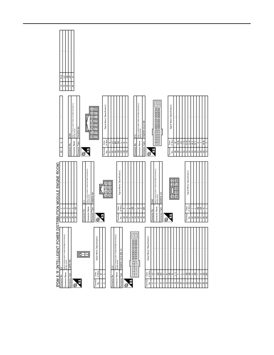
IPDM E/R (INTELLIGENT POWER DISTRIBUTION MODULE ENGINE ROOM)
Fail-safe
INFOID:0000000005516954
CAN COMMUNICATION CONTROL
When CAN communication with ECM and BCM is impossible, IPDM E/R performs fail-safe control. After CAN
communication recovers normally, it also returns to normal control.
If No CAN Communication Is Available With ECM
JCMWM4891GB