Nissan Murano Z51. Manual - part 91


  Главная      Nissan     Nissan Murano Z51 (2010 year) - Service Manual


поиск по сайту            


содержание   ..  89  90  91  92   ..


Nissan Murano Z51. Manual - part 91


AV

STEERING ANGLE SENSOR SIGNAL CIRCUIT

AV-143

< DTC/CIRCUIT DIAGNOSIS >

[BOSE AUDIO WITHOUT NAVIGATION]

C

D

E

F

G

H

I

J

K

L

M

B

A

O

P

STEERING ANGLE SENSOR SIGNAL CIRCUIT

Description

INFOID:0000000005528568

• Steering angle sensor signal 1, 2 detects the turning direction and quantity of the steering and transmits it to

the camera control unit.

• Steering angle sensor signal 3 detects the neutral position of the steering and transmits it to the camera con-

trol unit.

• Camera control unit performs the correction of neutral position with sensor signal 1, 2, 3 and vehicle speed

signal.

Diagnosis Procedure

INFOID:0000000005528569

1.

CHECK CONTINUITY STEERING ANGLE SENSOR SIGNAL CIRCUIT

1.

Turn ignition switch OFF.

2.

Disconnect camera control unit connector and steering angle sensor connector.

3.

Check continuity between camera control unit harness connector and steering angle sensor harness con-
nector.

4.

Check continuity between camera control unit harness connector and ground.

Is the inspection result normal?

YES

>> GO TO 2.

NO

>> Repair harness or connector.

2.

CHECK VOLTAGE CAMERA CONTROL UNIT

1.

Connect camera control unit connector.

2.

Turn ignition switch ON.

3.

Check voltage between camera control unit harness connector and ground.

Is the inspection result normal?

YES

>> GO TO 3.

NO

>> Replace camera control unit.

3.

CHECK STEERING ANGLE SENSOR SIGNAL

1.

Turn ignition switch OFF.

2.

Connect steering angle sensor connector.
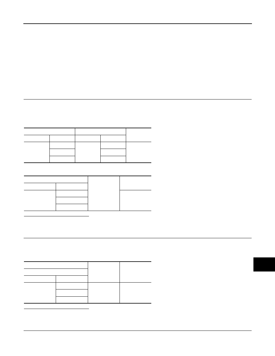
Camera control unit

Steering angle sensor

Continuity

Connector

Terminals

Connector

Terminals

B60

23

M30

3

Existed

24

6

25

8

Camera control unit

Ground

Continuity

Connector

Terminals

B60

23

Not existed

24

25

(+)

(

)

Reference value

(Approx.)

Camera control unit

Connector

Terminals

B60

23

Ground

5.0 V

24

25

AV-144

< DTC/CIRCUIT DIAGNOSIS >

[BOSE AUDIO WITHOUT NAVIGATION]

STEERING ANGLE SENSOR SIGNAL CIRCUIT

3.

Turn ignition switch ON.

4.

Check signal between camera control unit harness connector and ground.

Is the inspection result normal?

YES

>> INSPECTION END

NO

>> Replace steering angle sensor.

(+)

(

)

Condition

Reference value

Camera control unit

Connector

Terminals

B60

23, 24

Ground

Turn the steering to the right

A: Sensor signal 1
B: Sensor signal 2

Turn the steering to the left

A: Sensor signal 1
B: Sensor signal 2

25

Ground

Turn the steering around the 
neutral position

A: Sensor signal 3
B: Sensor signal 1

SKIB3827E

SKIB3828E

SKIB3829E

AV

STEERING SWITCH SIGNAL A CIRCUIT

AV-145

< DTC/CIRCUIT DIAGNOSIS >

[BOSE AUDIO WITHOUT NAVIGATION]

C

D

E

F

G

H

I

J

K

L

M

B

A

O

P

STEERING SWITCH SIGNAL A CIRCUIT

Description

INFOID:0000000005528570

Transmits the steering switch signal to AV control unit.

Diagnosis Procedure

INFOID:0000000005528571

1.

CHECK STEERING SWITCH SIGNAL A CIRCUIT

1.

Disconnect AV control unit connector and spiral cable connector. 

2.

Check continuity between AV control unit harness connector and spiral cable harness connector.

3.

Check continuity between AV control unit harness connector and ground.

Is the inspection result normal?

YES

>> GO TO 2.

NO

>> Repair harness or connector.

2.

CHECK SPIRAL CABLE

Check spiral cable. 
Is the inspection result normal?

YES

>> GO TO 3. 

NO

>> Replace spiral cable.

3.

CHECK AV CONTROL UNIT VOLTAGE

1.

Connect AV control unit connector and spiral cable connector.

2.

Turn ignition switch ON.

3.

Check voltage between AV control unit harness connector.

Is the inspection result normal?

YES

>> GO TO 4.

NO

>> Replace AV control unit.

4.

CHECK STEERING SWITCH

1.

Turn ignition switch OFF.

2.

Check steering switch. Refer to 

AV-146, "Component Inspection"

.

Is the inspection result normal?

YES

>> INSPECTION END

NO

>> Replace steering switch.

AV control unit

Spiral cable

Continuity

Connector

Terminal

Connector

Terminal

M127

6

M33

24

Existed

AV control unit

Ground

Continuity

Connector

Terminal

M127

6

Not existed

(+)

(

)

Voltage

(Approx.)

AV control unit

AV control unit

Connector

Terminal

Connector

Terminal

M127

6

M127

15

3.3 V

AV-146

< DTC/CIRCUIT DIAGNOSIS >

[BOSE AUDIO WITHOUT NAVIGATION]

STEERING SWITCH SIGNAL A CIRCUIT

Component Inspection

INFOID:0000000005528572

Measure the resistance between the steering switch connector ter-
minals 14 to 17 and 15 to 17.

Standard

JSNIA0216GB

Steering switch

Condition

Resistance 

Con-

nector

Termi-

nal

Con-

nector

Termi-

nal

M303

14

M303

17


switch 

ON

709 – 737

MENU DOWN switch 
ON

315 – 327

MENU UP switch ON

119 – 123

SOURCE switch ON

0

15

 switch ON

315 – 327

VOL UP switch ON

119 – 123

VOL DOWN switch ON

0


содержание   ..  89  90  91  92   ..