содержание .. 24 25 26 27 ..
Nissan Murano Z51. Manual - part 26
ADP-96
< DTC/CIRCUIT DIAGNOSIS >
MIRROR SENSOR
Is the inspection result normal?
YES
>> Replace automatic drive positioner control unit. Refer to
ADP-210, "Removal and Installation"
NO
>> Repair or replace harness or connector.
3.
CHECK DOOR MIRROR (DRIVER SIDE) SENSOR GROUND
1.
Turn ignition switch OFF.
2.
Disconnect automatic drive positioner control unit connector.
3.
Check continuity between automatic drive positioner control unit harness connector and door mirror
(driver side) harness connector.
Is the inspection result normal?
YES
>> GO TO 4.
NO
>> Repair or replace harness or connector.
4.
CHECK DOOR MIRROR (DRIVER SIDE) SENSOR CIRCUIT
1.
Check continuity between automatic drive positioner control unit harness connector and door mirror
(driver side) harness connector.
2.
Check continuity between automatic drive positioner control unit harness connector and ground.
Is the inspection result normal?
YES
>> Replace door mirror sensor. (Built in driver side mirror.)
NO
>> Repair or replace harness or connector.
PASSENGER SIDE
PASSENGER SIDE : Description
INFOID:0000000005515387
• The mirror sensor (passenger side) is installed to the door mirror (passenger side).
• The resistance of 2 sensors (horizontal and vertical) is changed when the door mirror (passenger side) is
operated.
• Automatic drive positioner control unit calculates the door mirror position according to the change of the volt-
age of 2 sensor input terminals.
PASSENGER SIDE : Component Function Check
INFOID:0000000005515388
1.
CHECK FUNCTION
1.
Select “MIR/SEN RH U-D”, “MIR/SEN RH R-L” in “Data monitor” with CONSULT-III.
2.
Check the mirror sensor (passenger side) signal under the following conditions.
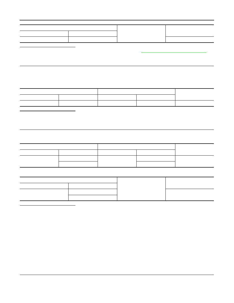
Automatic drive positioner control unit
Ground
Continuity
Connector
Terminal
M75
21
Not existed
Automatic drive positioner control unit
Door mirror (driver side)
Continuity
Connector
Terminal
Connector
Terminal
M75
20
D3
24
Existed
Automatic drive positioner control unit
Door mirror (driver side)
Continuity
Connector
Terminal
Connector
Terminal
M75
6
D3
21
Existed
18
22
Automatic drive positioner control unit
Ground
Continuity
Connector
Terminal
M75
6
Not existed
18