Nissan Murano Z51. Manual - part 11


  Главная      Nissan     Nissan Murano Z51 (2010 year) - Service Manual


поиск по сайту            


содержание   ..  9  10  11  12   ..


Nissan Murano Z51. Manual - part 11


ADP-36

< SYSTEM DESCRIPTION >

AUTOMATIC DRIVE POSITIONER SYSTEM

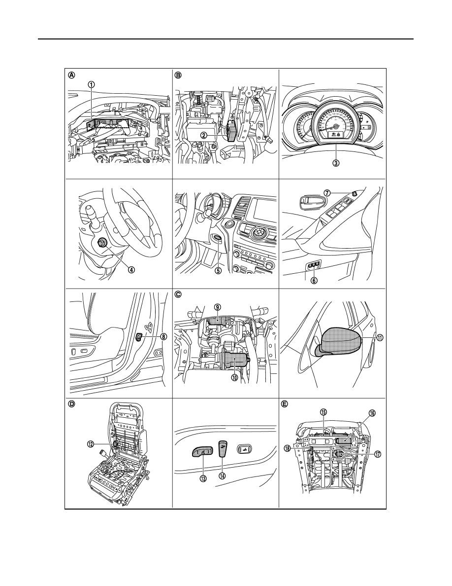
INTELLIGENT KEY INTERLOCK FUNCTION : Component Parts Location

INFOID:0000000005515295

1.

BCM M118, M119, M122, M123

2.

Automatic drive positioner control unit 
M75, M104

3.

Combination meter

4.

Tilt & telescopic switch M102

5.

Key slot M99

6.

Seat memory switch D13

7.

Door mirror remote control switch 
D14

8.

Front door switch (driver side) B34

9.

Tilt motor  M116

JMJIA1409ZZ

AUTOMATIC DRIVE POSITIONER SYSTEM

ADP-37

< SYSTEM DESCRIPTION >

C

D

E

F

G

H

I

K

L

M

A

B

ADP

N

O

P

INTELLIGENT KEY INTERLOCK FUNCTION : Component Description

INFOID:0000000005515296

CONTROL UNITS

10. Telescopic motor M117

11.

Door mirror (driver side) D3

12. Reclining motor B461

13. Sliding, Lifting switch

(Power seat switch B459)

14. Reclining switch

(Power seat switch B459)

15. Driver seat control unit B451,B452

16. Sliding motor B461

17. Lifting motor (front) B455

18. Lifting motor (rear) B456

A.

Behind the combination meter

B.

View with instrument driver lower 
panel removed

C.

View with instrument driver lower 
panel removed

D.

View with seat cushion and seatback 
pad removed

E.

Backside of the seat cushion

Item

Function

Driver seat control unit

It performs memory function and entry/exit assist function after receiving the door 
unlock signal from BCM.

Automatic drive positioner control unit

Operates the steering column and door mirror with the instructions from the driver 
seat control unit.

BCM

Recognizes the following status and transmits it to the driver seat control unit via 
CAN communication.
• Door lock: UNLOCK

 (with Intelligent Key or driver side door request switch)

• Key ID signal
• Ignition switch signal

ADP-38

< SYSTEM DESCRIPTION >

DIAGNOSIS SYSTEM (DRIVER SEAT CONTROL UNIT)

DIAGNOSIS SYSTEM (DRIVER SEAT CONTROL UNIT)

Diagnosis Description

INFOID:0000000005515297

The auto drive positioner system can be checked and diagnosed for component operation with CONSULT-III. 

DIAGNOSTIC MODE

CONSULT-III Function

INFOID:0000000005515298

SELF-DIAGNOSIS RESULTS

Refer to 

ADP-133, "DTC Index"

.

DATA MONITOR

Diagnostic mode

[AUTO DRIVE POS.]

Description

WORK SUPPORT

Changes the setting of each function.

SELF-DIAG RESULTS

Performs self-diagnosis for the auto drive positioner system and displays the results.

DATA MONITOR

Displays input signals transmitted from various switches and sensors to driver seat con-
trol unit in real time.

CAN DIAG SUPPORT MNTR

The result of transmit/receive diagnosis of CAN communication can be read.

ACTIVE TEST

Drive each output device.

ECU IDENTIFICATION

Displays part numbers of driver seat control unit parts.

Monitor Item

Unit

Main

Signals

Selection 

From 

Menu

Contents

SET SW

“ON/OFF”

×

×

ON/OFF status judged from the setting switch signal.

MEMORY SW 1

“ON/OFF”

×

×

ON/OFF status judged from the seat memory switch 1 sig-
nal.

MEMORY SW 2

“ON/OFF”

×

×

ON/OFF status judged from the seat memory switch 2 sig-
nal.

SLIDE SW–FR

“ON/OFF”

×

×

ON/OFF status judged from the sliding switch (forward) sig-
nal.

SLIDE SW–RR

“ON/OFF”

×

×

ON/OFF status judged from the sliding switch (backward) 
signal.

RECLN SW–FR

“ON/OFF”

×

×

ON/OFF status judged from the reclining switch (forward) 
signal.

RECLN SW–RR

“ON/OFF”

×

×

ON/OFF status judged from the reclining switch (backward) 
signal.

LIFT FR SW–UP

“ON/OFF”

×

×

ON/OFF status judged from the lifting switch front (up) sig-
nal.

LIFT FR SW–DN

“ON/OFF”

×

×

ON/OFF status judged from the lifting switch front (down) 
signal.

LIFT RR SW–UP

“ON/OFF”

×

×

ON/OFF status judged from the lifting switch rear (up) sig-
nal.

LIFT RR SW–DN

“ON/OFF”

×

×

ON/OFF status judged from the lifting switch rear (down) 
signal.

MIR CON SW–UP

“ON/OFF”

×

×

ON/OFF status judged from the mirror switch (up) signal.

MIR CON SW–DN

“ON/OFF”

×

×

ON/OFF status judged from the mirror switch (down) signal.

MIR CON SW–RH

“ON/OFF”

×

×

ON/OFF status judged from the door mirror remote control 
switch (passenger side) signal.

MIR CON SW–LH

“ON/OFF”

×

×

ON/OFF status judged from the door mirror remote control 
switch (driver side) signal.

DIAGNOSIS SYSTEM (DRIVER SEAT CONTROL UNIT)

ADP-39

< SYSTEM DESCRIPTION >

C

D

E

F

G

H

I

K

L

M

A

B

ADP

N

O

P

MIR CHNG SW–R

“ON/OFF”

×

×

ON/OFF status judged from the door mirror remote control 
switch (switching to right) signal.

MIR CHNG SW–L

“ON/OFF”

×

×

ON/OFF status judged from the door mirror remote control 
switch (switching to left) signal.

TILT SW-UP

“ON/OFF”

×

×

ON/OFF status judged from the tilt switch (up) signal.

TILT SW-DOWN

“ON/OFF”

×

×

ON/OFF status judged from the tilt switch (down) signal.

TELESCO SW-FR

“ON/OFF”

×

×

ON/OFF status judged from the telescoping switch (for-
ward) signal.

TELESCO SW-RR

“ON/OFF”

×

×

ON/OFF status judged from the telescoping switch (back-
ward) signal.

DETENT SW

“ON/OFF”

×

×

The selector lever position “OFF (P position) / ON (other 
than P position)” judged from the detention switch signal.

STARTER SW

“ON/OFF”

×

×

Ignition key switch ON (START, ON) /OFF (ACC, OFF) sta-
tus judged from the ignition switch signal.

SLIDE PULSE

×

Value (32768) when battery connections are standard. If it 
moves backward, the value increases. If it moves forward, 
the value decreases.

RECLN PULSE

×

Value (32768) when battery connections are standard. If it 
moves backward, the value increases. If it moves forward, 
the value decreases.

LIFT FR PULSE

×

Value (32768) when battery connections are standard. If it 
moves DOWN, the value increases. If it moves UP, the val-
ue decreases.

LIFT RR PULSE

×

Value (32768) when battery connections are standard. If it 
moves DOWN, the value increases. If it moves UP, the val-
ue decreases.

MIR/SEN RH U–D

“V”

×

Voltage input from door mirror sensor (passenger side) up/
down is displayed.

MIR/SEN RH R–L

“V”

×

Voltage input from door mirror sensor (passenger side) left/
right is displayed.

MIR/SEN LH U–D

“V”

×

Voltage input from door mirror sensor (driver side) up/down 
is displayed.

MIR/SEN LH R–L

“V”

×

Voltage input from door mirror sensor (driver side) left/right 
is displayed.

TILT PULSE

×

Value (32768) when battery connections are standard. If it 
moves DOWN, the value increases. If it moves UP, the val-
ue decreases.

TELESCO PULSE

×

Value (32768) when battery connections are standard. If it 
moves backward, the value increases. If it moves forward, 
the value decreases.

VEHICLE SPEED

×

×

Display the vehicle speed signal received from combination 
meter by numerical value [km/h].

P RANG SW CAN

“ON/OFF”

×

×

ON/OFF status judged from the P range switch signal.

R RANGE (CAN)

“ON/OFF”

×

×

ON/OFF status judged from the R range switch signal.

DOOR SW–FL

“ON/OFF”

×

×

ON/OFF status judged from the door switch (front driver 
side) signal.

DOOR SW–FR

“ON/OFF”

×

×

ON/OFF status judged from the door switch (front passen-
ger side) signal.

IGN ON SW

“ON/OFF”

×

×

ON/OFF status judged from the ignition switch signal.

ACC ON SW

“ON/OFF”

×

×

ON/OFF status judged from the ACC switch signal.

KEY ON SW

“ON/OFF”

×

×

ON/OFF status judged from the key on switch signal.

Monitor Item

Unit

Main

Signals

Selection 

From 

Menu

Contents


содержание   ..  9  10  11  12   ..