Murano Cross Cabriolet Z51 (2013 year). Manual - part 103


  Index      Manuals     Murano Cross Cabriolet Z51 (2013 year) - Service and Repair Manual


Search            copyright infringement  


Content      ..     101      102      103      104     ..


Murano Cross Cabriolet Z51 (2013 year). Manual - part 103


WCS-18

< ECU DIAGNOSIS INFORMATION >

COMBINATION METER

ECU DIAGNOSIS INFORMATION

COMBINATION METER

Reference Value

INFOID:0000000008955006

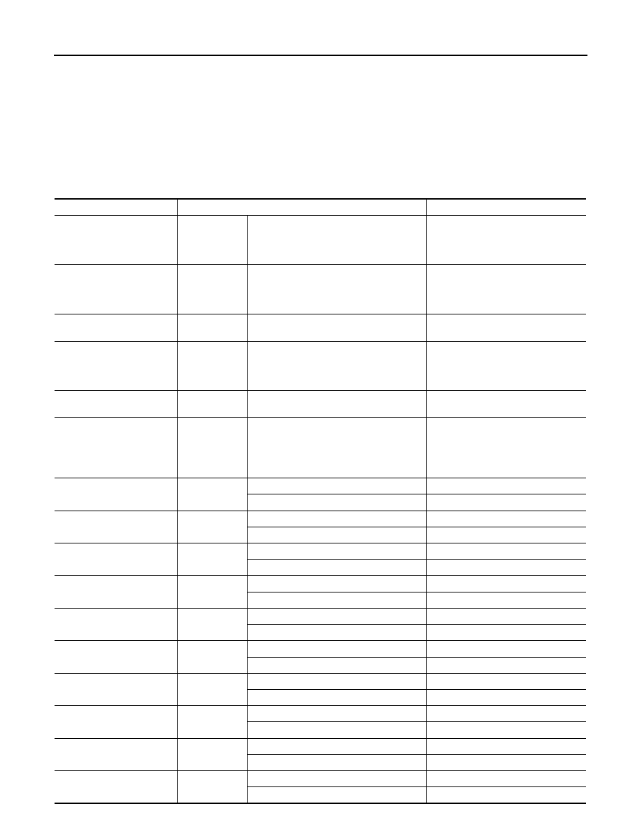
VALUES ON THE DIAGNOSIS TOOL

NOTE:
The following table includes information (items) inapplicable to this vehicle. For information (items) applicable
to this vehicle, refer to CONSULT display items.

Monitor Item

Condition

Value/Status

SPEED METER
[km/h]

Ignition switch 
ON

While driving

Equivalent to speedometer reading
NOTE:
655.35 is displayed when the malfunc-
tion signal is received

SPEED OUTPUT
[km/h]

Ignition switch 
ON

While driving

Equivalent to speedometer reading
NOTE:
655.35 is displayed when the malfunc-
tion signal is received

ODO OUTPUT
[km/h or mph]

Ignition switch 
ON

Equivalent to odometer reading in 
combination meter

TACHO METER
[rpm]

Ignition switch 
ON

While driving

Equivalent to tachometer reading
NOTE:
8191.875 is displayed when the mal-
function signal is received

FUEL METER
[L]

Ignition switch 
ON

Values according to fuel level

W TEMP METER
[

°

C]

Ignition switch 
ON

Values according to engine coolant 
temperature
NOTE:
215 is displayed when the malfunction 
signal is input

ABS W/L

Ignition switch 
ON

ABS warning lamp ON

On

ABS warning lamp OFF

Off

VDC/TCS IND

Ignition switch 
ON

VDC OFF indicator lamp ON

On

VDC OFF indicator lamp OFF

Off

SLIP IND

Ignition switch 
ON

VDC warning lamp ON

On

VDC warning lamp OFF

Off

BRAKE W/L

Ignition switch 
ON

Brake warning lamp ON

On

Brake warning lamp OFF

Off

DOOR W/L

Ignition switch 
ON

Door warning ON

On

Door warning OFF

Off

TRUNK/GLAS-H

Ignition switch 
ON

Trunk warning ON

On

Trunk warning OFF

Off

HI-BEAM IND

Ignition switch 
ON

High-beam indicator lamp ON

On

High-beam indicator lamp OFF

Off

TURN IND

Ignition switch 
ON

Turn signal indicator lamp ON

On

Turn signal indicator lamp OFF

Off

LIGHT IND

Ignition switch 
ON

Light indicator lamp ON

On

Light indicator lamp OFF

Off

OIL W/L 

Ignition switch 
ON

Oil pressure warning lamp ON

On

Oil pressure warning lamp OFF

Off

Revision: 2012 October

2013 Murano CrossCabriolet

WCS

COMBINATION METER

WCS-19

< ECU DIAGNOSIS INFORMATION >

C

D

E

F

G

H

I

J

K

L

M

B

A

O

P

MIL

Ignition switch 
ON

Malfunction indicator lamp ON

On

Malfunction indicator lamp OFF

Off

CRUISE IND

Ignition switch 
ON

CRUISE indicator lamp ON

On

CRUISE indicator lamp OFF

Off

O/D OFF IND

Ignition switch 
ON

O/D OFF indicator lamp ON

On

O/D OFF indicator lamp OFF

Off

4WD W/L

Ignition switch 
ON

AWD warning lamp ON

On

AWD warning lamp OFF

Off

4WD LOCK IND

Ignition switch 
ON

AWD LOCK indicator lamp ON

On

AWD LOCK indicator lamp OFF

Off

FUEL W/L

Ignition switch 
ON

Low-fuel warning lamp ON

On

Low-fuel warning lamp OFF

Off

WASHER W/L

Ignition switch 
ON

Washer warning displayed

On

Washer warning not displayed

Off

AIR PRES W/L

Ignition switch 
ON

Low tire pressure warning lamp ON

On

Low tire pressure warning lamp OFF

Off

KEY G/Y W/L 

Ignition switch 
ON

Key warning lamp (green/yellow) ON

On

Key warning lamp (green/yellow) OFF

Off

LCD

Ignition switch 
ON

Engine start information display

B&P I

Ignition switch 
ACC

Engine start information display

B&P N

Ignition switch 
LOCK

Key ID warning display

ID NG

Ignition switch 
LOCK

Steering lock information display

ROTAT

Ignition switch 
LOCK

P position warning display

SFT P

Ignition switch 
LOCK

Intelligent Key insert information display

INSRT

Ignition switch 
LOCK

Intelligent Key low battery warning display

BATT

Ignition switch 
ON

Take away warning display

NO KY

Ignition switch 
LOCK

Key warning display

OUTKY

Ignition switch 
ON

ACC warning display

LK WN

SHIFT IND

Ignition switch 
ON

Shift position indicator P display

P

Shift position indicator R display

R

Shift position indicator N display

N

Shift position indicator D display

D

Shift position indicator L display

L

FUEL CAP W/L

Ignition switch 
ON

Fuel filler cap warning display ON

On

Fuel filler cap warning display OFF

Off

O/D OFF SW

Ignition switch 
ON

Overdrive control switch ON

On

Overdrive control switch OFF

Off

Monitor Item

Condition

Value/Status

Revision: 2012 October

2013 Murano CrossCabriolet

WCS-20

< ECU DIAGNOSIS INFORMATION >

COMBINATION METER

NOTE:

Some items are not available according to vehicle specification.

TERMINAL LAYOUT

M RANGE SW

Ignition switch 
ON

NOTE:
This item is displayed, but cannot be moni-
tored.

Off

NM RANGE SW

Ignition switch 
ON

NOTE:
This item is displayed, but cannot be moni-
tored.

Off

AT SFT UP SW

Ignition switch 
ON

NOTE:
This item is displayed, but cannot be moni-
tored.

Off

AT SFT DWN SW

Ignition switch 
ON

NOTE:
This item is displayed, but cannot be moni-
tored.

Off

PKB SW

Ignition switch 
ON

Parking brake switch ON

On

Parking brake switch OFF

Off

BUCKLE SW

Ignition switch 
ON

Seat belt (driver side) not fastened

On

Seat belt (driver side) fastened

Off

BRAKE OIL SW

Ignition switch 
ON

Brake fluid level switch ON

On

Brake fluid level switch OFF

Off

A/C AMP CONN

Ignition switch 
ON

Other than the following

On

Receives ambient sensor power signal

Off

ENTER SW

Ignition switch 
ON

When 

 is pressed

On

Other than the above

Off

SELECT SW

Ignition switch 
ON

When 

 is pressed

On

Other than the above

Off

DISTANCE
[km]

Ignition switch 
ON

Distance to empty calculated by com-
bination meter

OUTSIDE TEMP
[

°

C] or [

°

F]

Ignition switch 
ON

Equivalent to ambient temperature
NOTE:
This may not match the indicated value 
on the information display.

FUEL LOW SIG

Ignition switch 
ON

Low fuel warning displayed

On

Low fuel warning not displayed

Off

BUZZER

Ignition switch 
ON

Buzzer ON

On

Buzzer OFF

Off

TPMS PRESS L

Power switch 
ON

During check tire pressure warning indica-
tion

On

Other than the above

Off

Monitor Item

Condition

Value/Status

JPNIA0968GB

Revision: 2012 October

2013 Murano CrossCabriolet

WCS

COMBINATION METER

WCS-21

< ECU DIAGNOSIS INFORMATION >

C

D

E

F

G

H

I

J

K

L

M

B

A

O

P

PHYSICAL VALUES

Terminal No.

(Wire color)

Description

Condition

Value

(Approx.)

+

Signal name

Input/

Output

1

(Y)

Ground

Battery power supply

Input

Ignition 
switch 
OFF

Battery voltage

2

(O)

Ground

Ignition signal

Input

Ignition 
switch 
ON

Battery voltage

3

(B)

Ground

Ground

Ignition 
switch 
ON

0  V

4

(B)

Ground

Ground

Ignition 
switch 
ON

0  V

5

(SB)

Ground

Illumination control signal

Output

Ignition 
switch 
ON

• Lighting switch 1ST
• When meter illumination 

is maximum

• Lighting switch 1ST
• When meter illumination 

is minimum

8

(SB)

10

(O)

Trip reset signal

Input

Ignition 
switch 
ON

When trip reset switch is 
pressed.

0 V

Other than the above

5 V

9

(W)

Ground

Illumination control signal 
(illumination control switch)

Output

Ignition 
switch 
ON

• Lighting switch 1ST
• When meter illumination 

is maximum

• Lighting switch 1ST
• When meter illumination 

is minimum

10

(O)

Ground

Meter control switch ground

Ignition 
switch 
ON

0  V

JPNIA0828GB

JSNIA4277GB

JSNIA4278GB

JSNIA4279GB

Revision: 2012 October

2013 Murano CrossCabriolet

WCS-22

< ECU DIAGNOSIS INFORMATION >

COMBINATION METER

11

(L)

10

(O)

Enter switch signal

Input

Ignition 
switch 
ON

When  

is 

pressed.

0 V

Other than the above

5 V

12

(R)

10

(O)

Select switch signal

Input

Ignition 
switch 
ON

When 

 is pressed.

0 V

Other than the above

5 V

13

(V)

10

(O)

Illumination control switch 
signal (+)

Input

Ignition 
switch 
ON

When  

is 

pressed.

0 V

Other than the above

5 V

14

(GR)

10

(O)

Illumination control switch 
signal (-)

Input

Ignition 
switch 
ON

When  

is 

pressed.

0 V

Other than the above

5 V

15

(BR)

Air bag signal

Input

18

(L)

Ground

Ambient sensor signal

Input

Ignition 
switch 
ON

Changes depending to am-
bient temperature.

19

(P)

Ground

A/C auto amp. connection 
recognition signal

Input

Ignition 
switch 
ON

5  V

20

(Y)

Ground

Ambient sensor ground

Input

Ignition 
switch 
ON

0  V

21

(L)

CAN-H

22

(P)

CAN-L

23

(B)

Ground

Ground

Ignition 
switch 
ON

0  V

24

(W)

Ground

Fuel level sensor ground

Ignition 
switch 
ON

0  V

25

(BR)

Ground

Alternator signal

Input

Ignition 
switch 
ON

Charge warning lamp ON

2 V

Charge warning lamp OFF

12 V

26

(G)

Ground

Parking brake switch signal

Input

Ignition 
switch 
ON

Parking brake ON

0 V

Parking brake OFF

5 V

27

(V)

Ground

Brake fluid level switch sig-
nal

Input

Ignition 
switch 
ON

Brake fluid level is normal

12 V

Brake fluid level is less than 
LOW level

0 V

28

(R)

Ground

Roof status signal

Input

Ignition 
switch 
ON

Soft top indicator lamp ON

0 V

Soft top indicator lamp OFF

12 V

29

(R)

Ground

Washer level switch signal

Input

Ignition 
switch 
ON

Washer level switch ON

0 V

Washer level switch OFF

5 V

Terminal No.

(Wire color)

Description

Condition

Value

(Approx.)

+

Signal name

Input/

Output

JSNIA0014GB

Revision: 2012 October

2013 Murano CrossCabriolet

WCS

COMBINATION METER

WCS-23

< ECU DIAGNOSIS INFORMATION >

C

D

E

F

G

H

I

J

K

L

M

B

A

O

P

Fail-Safe

INFOID:0000000008955007

FAIL-SAFE

The combination meter activates the fail-safe control if CAN communication with each unit is malfunctioning.

30

(P)

Ground

Vehicle speed signal
(2-pulse)

Output

Ignition 
switch 
ON

Speedometer operated 
[When vehicle speed is ap-
prox. 40 km/h (25 MPH)]

NOTE:
The maximum voltage varies de-
pending on the specification 
(destination unit).

31

(V)

Ground

Vehicle speed signal
(8-pulse)

Output

Ignition 
switch 
ON

Speedometer operated 
[When vehicle speed is ap-
prox. 40 km/h (25 MPH)]

NOTE:
The maximum voltage varies de-
pending on the specification 
(destination unit).

32

(LG)

Ground

Overdrive control switch 
signal

Input

Ignition 
switch 
ON

Overdrive control switch 
pressed.

0 V

Overdrive control switch 
not pressed.

5 V

34

(G)

Ground

Fuel level sensor signal

Input

Ignition 
switch 
ON

MWI-49, "Component Inspec-
tion"

35

(SB)

Ground

Seat belt buckle switch sig-
nal (driver side)

Input

Ignition 
switch 
ON

When driver seat belt is fas-
tened.

12 V

When driver seat belt is un-
fastened.

0 V

36

(R)

Seat belt buckle switch sig-
nal (passenger side)

Input

Terminal No.

(Wire color)

Description

Condition

Value

(Approx.)

+

Signal name

Input/

Output

JSNIA0015GB

JSNIA0012GB

Function

Specifications

Speedometer

Reset to zero by suspending communication.

Tachometer

Engine coolant temperature gauge

Illumination control

When suspending communication, changes to nighttime 
mode.

Revision: 2012 October

2013 Murano CrossCabriolet

WCS-24

< ECU DIAGNOSIS INFORMATION >

COMBINATION METER

DTC Index

INFOID:0000000008955008

Information display

Door open warning

The display turns off by suspending communication.

Trunk open warning

Parking brake release warning

Low tire pressure warning

Fuel filler cap warning

Instantaneous fuel warning

• When reception time of an abnormal signal is 2 seconds or 

less, the last received datum is used for calculation to indi-
cate the result.

• When reception time of an abnormal signal is more than two 

seconds, the last result calculated during normal condition 
is indicated.

Average fuel consumption

Average vehicle speed

Travel distance

Buzzer

The buzzer turns off by suspending communication.

Warning lamp/indicator 
lamp

ABS warning lamp

The lamp turns on by suspending communication.

VDC warning lamp

Brake warning lamp

AWD warning lamp

Malfunction indicator lamp

Low tire pressure warning lamp

The lamp turns ON after flashing for 1 minute.

High beam indicator lamp

The lamp turns off by suspending communication.

Turn signal indicator lamp

Light indicator lamp

Oil pressure warning lamp

CRUISE indicator lamp

O/D OFF indicator lamp

VDC OFF indicator lamp

AWD LOCK indicator lamp

Key warning lamp

Function

Specifications

Display contents of CONSULT

Diagnostic item is detected when ...

Refer to

CAN COMM CIRCUIT
[U1000]

When combination meter is not transmitting or receiving CAN communication signal 
for 2 seconds or more.

MWI-42, 

"Diagnosis

Procedure"

CONTROL UNIT (CAN)
[U1010]

When detecting error during the initial diagnosis of the CAN controller of combina-
tion meter.

MWI-43, 

"Diagnosis 

Procedure"

VEHICLE SPEED
[B2205]

The abnormal vehicle speed signal is input from the ABS actuator and electric unit 
(control unit) for 2 seconds or more.

MWI-44, 

"Diagnosis

Procedure"

ENGINE SPEED
[B2267]

If ECM continuously transmits abnormal engine speed signals for 2 seconds or 
more.

MWI-45, 

"Diagnosis 

Procedure"

WATER TEMP
[B2268]

If ECM continuously transmits abnormal engine coolant temperature signals for 60 
seconds or more.

MWI-46, 

"Diagnosis 

Procedure"

Revision: 2012 October

2013 Murano CrossCabriolet

WCS

BCM (BODY CONTROL MODULE)

WCS-25

< ECU DIAGNOSIS INFORMATION >

C

D

E

F

G

H

I

J

K

L

M

B

A

O

P

BCM (BODY CONTROL MODULE)

List of ECU Reference

INFOID:0000000008462220

ECU

Reference

BCM

BCS-32, "Reference Value"

BCS-54, "Fail-safe"

BCS-54, "DTC Inspection Priority Chart"

BCS-55, "DTC Index"

Revision: 2012 October

2013 Murano CrossCabriolet

WCS-26

< WIRING DIAGRAM >

WARNING CHIME SYSTEM

WIRING DIAGRAM

WARNING CHIME SYSTEM

Wiring Diagram

INFOID:0000000008462221

For connector terminal arrangements, harness layouts, and alphabets in a 

 (option abbreviation; if not

described in wiring diagram), refer to 

GI-12, "Connector Information"

.

JRNWC2908GB

Revision: 2012 October

2013 Murano CrossCabriolet

WCS

DIAGNOSIS AND REPAIR WORKFLOW

WCS-27

< BASIC INSPECTION >

C

D

E

F

G

H

I

J

K

L

M

B

A

O

P

BASIC INSPECTION

DIAGNOSIS AND REPAIR WORKFLOW

Work Flow

INFOID:0000000008462222

OVERALL SEQUENCE

DETAILED FLOW

1.

OBTAIN INFORMATION ABOUT SYMPTOM

Interview the customer to obtain as much information as possible about the conditions and environment under
which the malfunction occurred.

>> GO TO 2.

2.

CHECK SYMPTOM

• Check the symptom based on the information obtained from the customer.
• Check if any other malfunctions are present.

>> GO TO 3.

3.

CHECK CONSULT SELF-DIAGNOSIS RESULTS

1.

Connect CONSULT and perform self-diagnosis. Refer to 

WCS-24, "DTC Index"

.

2.

When DTC is detected, follow the instructions below:

-

Record DTC and Freeze Frame Data.

Are self-diagnosis results normal?

YES

>> GO TO 4.

NO

>> GO TO 5.

JSNIA4492GB

Revision: 2012 October

2013 Murano CrossCabriolet

WCS-28

< BASIC INSPECTION >

DIAGNOSIS AND REPAIR WORKFLOW

4.

NARROW DOWN MALFUNCTIONING PARTS BY SYMPTOM DIAGNOSIS

Perform symptom diagnosis and narrow down the malfunctioning parts.

>> GO TO 5.

5.

REPAIR OR REPLACE MALFUNCTIONING PARTS

Repair or replace malfunctioning parts.
NOTE:
If DTC is displayed, erase DTC after repairing or replacing malfunctioning parts.

>> GO TO 6.

6.

FINAL CHECK

Check that the warning buzzer in the combination meter operates normally.

Does it operate normally?

YES

>> INSPECTION END

NO

>> GO TO 1.

Revision: 2012 October

2013 Murano CrossCabriolet

WCS

POWER SUPPLY AND GROUND CIRCUIT

WCS-29

< DTC/CIRCUIT DIAGNOSIS >

C

D

E

F

G

H

I

J

K

L

M

B

A

O

P

DTC/CIRCUIT DIAGNOSIS

POWER SUPPLY AND GROUND CIRCUIT

COMBINATION METER

COMBINATION METER : Diagnosis Procedure

INFOID:0000000008954776

1.

CHECK FUSE

Check for blown fuses.

Is the inspection result normal?

YES

>> GO TO 2.

NO

>> Be sure to eliminate cause of malfunction before installing new fuse.

2.

CHECK POWER SUPPLY CIRCUIT

Check voltage between combination meter harness connector terminals and ground.

Is the inspection result normal?

YES

>> GO TO 3.

NO

>> Check harness between combination meter and fuse.

3.

CHECK GROUND CIRCUIT

1.

Turn ignition switch OFF.

2.

Disconnect combination meter connector.

3.

Check continuity between combination meter harness connector terminals and ground.

Is the inspection result normal?

YES

>> INSPECTION END

NO

>> Repair harness or connector.

Power source

Fuse No.

Battery

6

Ignition switch ON or START 

4

Terminals

Ignition switch po-

sition

Voltage

(Approx.)

(+)

(-)

Combination meter

Ground

Connector

Terminal

M34

1

OFF

Battery voltage

2

ON

Terminals

Continuity

(+)

(-)

Combination meter

Ground

Connector

Terminal

M34

3

Existed

4

23

Revision: 2012 October

2013 Murano CrossCabriolet

WCS-30

< DTC/CIRCUIT DIAGNOSIS >

METER BUZZER CIRCUIT

METER BUZZER CIRCUIT

Description

INFOID:0000000008462224

• The buzzer for warning chime system is installed in the combination meter.
• The combination meter sounds the alarm buzzer based on the signals transmitted from various units.

Component Function Check

INFOID:0000000008462225

1.

CHECK OPERATION OF METER BUZZER

1.

Select “BUZZER” of “BCM” on CONSULT.

2.

Perform “LIGHT WARN ALM” of “Active Test”.

Does meter buzzer beep?

YES

>> INSPECTION END

NO

>> GO TO 2.

2.

CHECK COMBINATION METER INPUT SIGNAL

Select the “Data Monitor” for the “METER/M&A” and check the “BUZZER” monitor value.

Is the inspection result normal?

YES

>> Replace combination meter.

NO

>> Replace BCM. Refer to 

BCS-77, "Removal and Installation"

.

Diagnosis Procedure

INFOID:0000000008462226

1.

CHECK POWER SUPPLY OF COMBINATION METER

Check power supply of combination meter. Refer to 

MWI-47, "COMBINATION METER : Diagnosis Proce-

dure"

.

Is the inspection result normal?

YES

>> INSPECTION END

NO

>> Repair power supply circuit of combination meter. Refer to 

MWI-47, "COMBINATION METER :

Diagnosis Procedure"

.

BUZZER

Under the condition of buzzer input

: On

Except above

: Off

Revision: 2012 October

2013 Murano CrossCabriolet

WCS

SEAT BELT BUCKLE SWITCH SIGNAL CIRCUIT

WCS-31

< DTC/CIRCUIT DIAGNOSIS >

C

D

E

F

G

H

I

J

K

L

M

B

A

O

P

SEAT BELT BUCKLE SWITCH SIGNAL CIRCUIT

Description

INFOID:0000000008462227

Transmits a seat belt buckle switch signal (driver side) to the combination meter.

Component Function Check

INFOID:0000000008462228

1.

CHECK COMBINATION METER INPUT SIGNAL

Select the “Data Monitor” for the “METER/M&A” and check the “BUCKLE SW” monitor value.

>> INSPECTION END

Diagnosis Procedure

INFOID:0000000008462229

1.

CHECK COMBINATION METER INPUT SIGNAL

1.

Turn ignition switch ON.

2.

Check voltage between combination meter harness connector terminal and ground.

Is the inspection result normal?

YES

>> Replace combination meter. Refer to 

MWI-70, "Removal and Installation"

.

NO

>> GO TO 2.

2.

CHECK SEAT BELT BUCKLE SWITCH CIRCUIT

1.

Turn ignition switch OFF.

2.

Disconnect combination meter connector and seat belt buckle switch (driver side) connector.

3.

Check continuity between combination meter harness connector terminal and seat belt buckle switch
(driver side) harness connector terminal.

4.

Check harness continuity between combination meter harness connector terminal and ground.

Is the inspection result normal?

BUCKLE SW

When seat belt is fastened

: Off

When seat belt is unfastened

: On

Terminals

Condition

Voltage

(Approx.)

(+)

(-)

Combination meter

Ground

Connector

Terminal

M34

35

When seat belt is fastened

12 V

When seat belt is unfastened

0 V

Terminals

Continuity

(+)

(-)

Combination meter

Seat belt buckle switch(driver side)

Connector

Terminal

Connector

Terminal

M34

35

B449

40

Exist

Terminals

Continuity

(+)

(-)

Combination meter

Ground

Connector

Terminal

M34

35

Not existed

Revision: 2012 October

2013 Murano CrossCabriolet

WCS-32

< DTC/CIRCUIT DIAGNOSIS >

SEAT BELT BUCKLE SWITCH SIGNAL CIRCUIT

YES

>> GO TO 3.

NO

>> Repair harness or connector.

3.

CHECK SEAT BELT BUCKLE SWITCH GROUND CIRCUIT

Check harness continuity between seat belt buckle switch (driver side) harness connector terminal and
ground.

Is the inspection result normal?

YES

>> INSPECTION END

NO

>> Repair harness or connector.

Component Inspection

INFOID:0000000008462230

1.

CHECK SEAT BELT BUCKLE SWITCH (DRIVER SIDE)

1.

Turn ignition switch OFF.

2.

Disconnect the seat belt buckle switch (driver side) connector.

3.

Check continuity between terminals.

Is the inspection result normal?

YES

>> INSPECTION END

NO

>> Replace the seat belt buckle. Refer to 

SB-7, "SEAT BELT BUCKLE : Removal and Installation"

.

Terminals

Continuity

(+)

(-)

Combination  meter

Ground

Connector

Terminal

B449

41

Exist

Terminals

Condition

Continuity

(+)

(-)

Seat belt buckle switch (driver side)

Connector

Terminal

Connector

Terminal

B449

40

B449

41

When seat belt is fastened

Not existed

When seat belt is unfastened

Exist

Revision: 2012 October

2013 Murano CrossCabriolet

WCS

THE PARKING BRAKE RELEASE WARNING CONTINUES SOUNDING, OR 

DOES NOT SOUND

WCS-33

< SYMPTOM DIAGNOSIS >

C

D

E

F

G

H

I

J

K

L

M

B

A

O

P

SYMPTOM DIAGNOSIS

THE PARKING BRAKE RELEASE WARNING CONTINUES SOUNDING, OR
DOES NOT SOUND

Description

INFOID:0000000008462231

• The parking brake warning buzzer sounds continuously during vehicle travel though the parking brake is

released.

• The parking brake warning buzzer does not sound at all even though driving the vehicle with the parking

brake applied.

Diagnosis Procedure

INFOID:0000000008462232

1.

CHECK PARKING BRAKE WARNING LAMP

1.

Start the engine.

2.

Check the operation of the brake warning lamp by operating the parking brake.

Is the inspection result normal?

YES

>> Replace the combination meter. Refer to 

MWI-70, "Removal and Installation"

.

NO

>> GO TO 2.

2.

CHECK PARKING BRAKE SWITCH SIGNAL CIRCUIT

Perform a check for the parking brake switch signal circuit. Refer to 

MWI-56, "Diagnosis Procedure"

.

Is the inspection result normal?

YES

>> GO TO 3.

NO

>> Repair harness or connector.

3.

CHECK PARKING BRAKE SWITCH

Perform a unit check for the parking brake switch. Refer to 

MWI-56, "Component Inspection"

.

Is the inspection result normal?

YES

>> Replace the combination meter. Refer to 

MWI-70, "Removal and Installation"

.

NO

>> Replace the parking brake switch. Refer to 

PB-6, "Exploded View"

.

When parking brake is applied

: ON

When parking brake is released

: OFF

Revision: 2012 October

2013 Murano CrossCabriolet


Content      ..     101      102      103      104     ..