Murano Cross Cabriolet Z51 (2013 year). Manual - part 20
C1110 ABS ACTUATOR AND ELECTRIC UNIT (CONTROL UNIT)
BRC-45
< DTC/CIRCUIT DIAGNOSIS >
[WITH VDC]
C
D
E
G
H
I
J
K
L
M
A
B
BRC
N
O
P
C1110 ABS ACTUATOR AND ELECTRIC UNIT (CONTROL UNIT)
DTC Logic
INFOID:0000000008462515
DTC DETECTION LOGIC
DTC CONFIRMATION PROCEDURE
1.
PRECONDITIONING
If “DTC CONFIRMATION PROCEDURE” has been previously conducted, always turn the ignition switch OFF
and wait at least 10 seconds before conducting the next test.
>> GO TO 2.
2.
DTC REPRODUCTION PROCEDURE
1.
Turn the ignition switch OFF to ON.
2.
Perform self-diagnosis for “ABS” with CONSULT.
Is DTC “C1110” detected?
YES
>> Proceed to diagnosis procedure. Refer to
.
NO
>> INSPECTION END
Diagnosis Procedure
INFOID:0000000008462516
1.
REPLACE ABS ACTUATOR AND ELECTRIC UNIT (CONTROL UNIT)
Replace ABS actuator and electric unit (control unit) when self-diagnostic result shows items other than those
applicable.
>> Replace ABS actuator and electric unit (control unit). Refer to
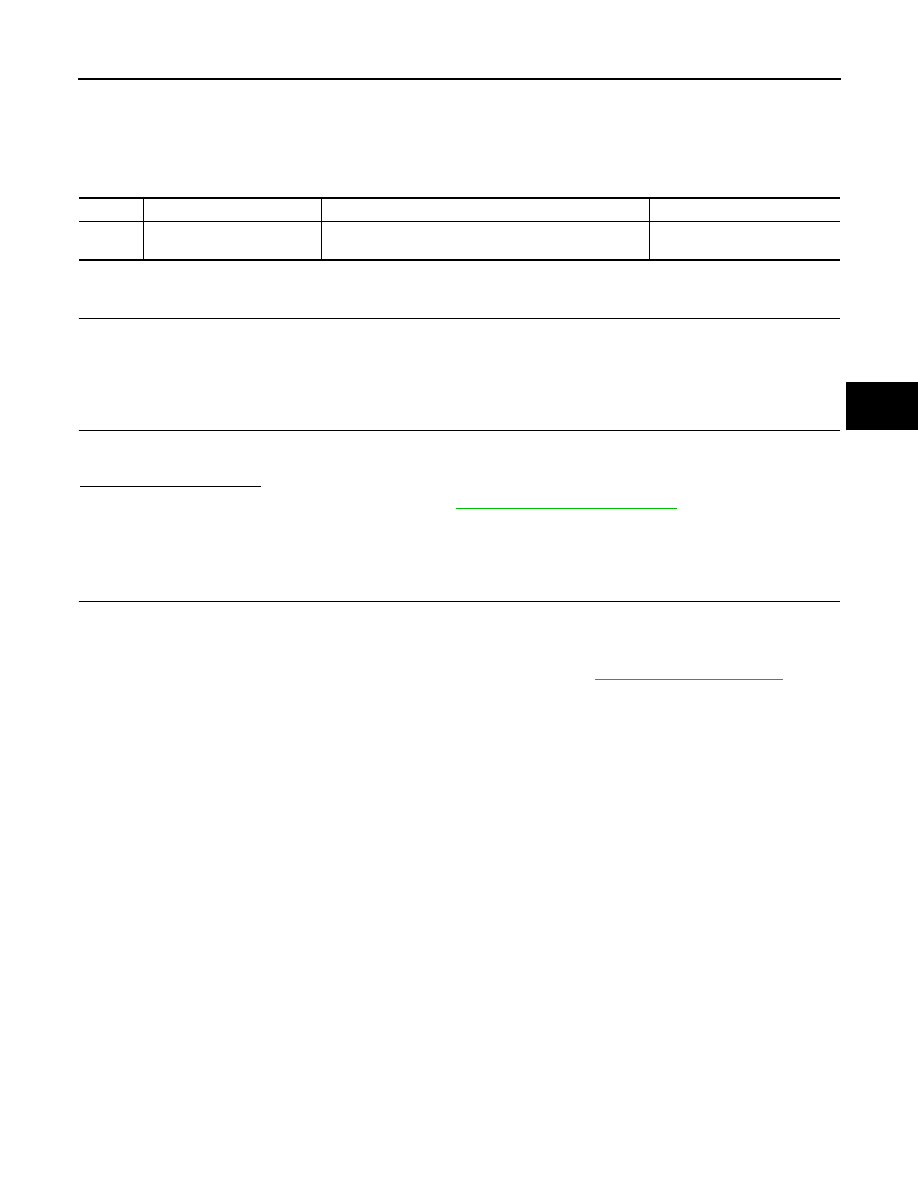
DTC
Display item
Malfunction detected condition
Possible cause
C1110
CONTROLLER FAILURE
When there is an internal malfunction in the ABS actuator
and electric unit (control unit).
ABS actuator and electric unit
(control unit)
Revision: 2012 October
2013 Murano CrossCabriolet