Murano Cross Cabriolet Z51 (2013 year). Manual - part 9


  Index      Manuals     Murano Cross Cabriolet Z51 (2013 year) - Service and Repair Manual


Search            copyright infringement  


Content      ..     7      8      9      10     ..


Murano Cross Cabriolet Z51 (2013 year). Manual - part 9


POWER WALK-IN SWITCH

ADP-125

< REMOVAL AND INSTALLATION >

C

D

E

F

G

H

I

K

L

M

A

B

ADP

N

O

P

POWER WALK-IN SWITCH

Removal and Installation

INFOID:0000000008463675

REMOVAL

1.

Remove driver seat. Refer to 

SE-28, "Removal and Installation"

.

2.

Remove seatback pad and power walk-in switch escutcheon. Refer to 

SE-30, "SEATBACK : Disassembly

and Assembly"

.

3.

Disconnect power walk-in switch harness connector.
NOTE:
Slightly lift up seatback pad so that harness connector is removed.
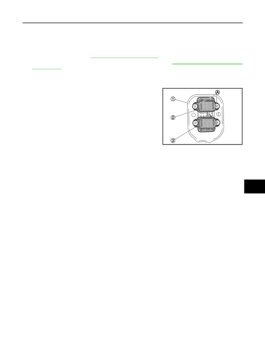
4.

Remove screws (A) while mounting seat trim, and then remove
power walk-in switch (2) from seatback frame assembly (1).
Remove power walk-in switch (3) in the same procedures.

INSTALLATION

Install in the reverse order of removal.

JMJIA6330ZZ

Revision: 2012 October

2013 Murano CrossCabriolet

ADP-126

< REMOVAL AND INSTALLATION >

TILT&TELESCOPIC SWITCH

TILT&TELESCOPIC SWITCH

Removal and Installation

INFOID:0000000008463676

REMOVAL

1.

Remove steering column mask. Refer to 

IP-13, "Removal and

Installation"

.

2.

Press pawls and remove tilt & telescopic switch (2) from steering
column mask (1).

INSTALLATION

Install in the reverse order of removal.

: Pawl

JMJIA1467ZZ

Revision: 2012 October

2013 Murano CrossCabriolet

BCS

BCS-1

ELECTRICAL & POWER CONTROL

C

D

E

F

G

H

I

J

K

L

B

SECTION 

BCS

A

O

P

N

CONTENTS

BODY CONTROL SYSTEM

PRECAUTION ...............................................

3

PRECAUTIONS ...................................................

3

Precaution for Supplemental Restraint System 
(SRS) "AIR BAG" and "SEAT BELT PRE-TEN-
SIONER" .................................................................
..

3

Service Procedure Precautions for Models with a 
Pop-up Roll Bar .......................................................
..

3

SYSTEM DESCRIPTION  ..............................

4

COMPONENT PARTS  ........................................

4

BODY CONTROL SYSTEM  ........................................

4

BODY CONTROL SYSTEM : Component Parts 
Location ...................................................................
..

4

POWER CONSUMPTION CONTROL SYSTEM  .........

4

POWER CONSUMPTION CONTROL SYSTEM : 
Component Parts Location ......................................
..

4

SYSTEM ..............................................................

5

BODY CONTROL SYSTEM  ........................................

5

BODY CONTROL SYSTEM : System Description 

......

5

COMBINATION SWITCH READING SYSTEM  ...........

6

COMBINATION SWITCH READING SYSTEM : 
System Diagram ......................................................
..

6

COMBINATION SWITCH READING SYSTEM : 
System Description  .................................................
..

6

SIGNAL BUFFER SYSTEM  ........................................

9

SIGNAL BUFFER SYSTEM : System Diagram  ........

9

SIGNAL BUFFER SYSTEM : System Description 

......

9

POWER CONSUMPTION CONTROL SYSTEM  .......

10

POWER CONSUMPTION CONTROL SYSTEM : 
System Diagram ......................................................

10

POWER CONSUMPTION CONTROL SYSTEM : 
System Description  .................................................

10

DIAGNOSIS SYSTEM (BCM)  ............................

12

COMMON ITEM  .........................................................

12

COMMON ITEM : CONSULT Function (BCM - 
COMMON ITEM)  .....................................................

12

DOOR LOCK ..............................................................

13

DOOR LOCK : CONSULT Function (BCM - 
DOOR LOCK) ..........................................................

13

REAR WINDOW DEFOGGER  ...................................

14

REAR WINDOW DEFOGGER : CONSULT Func-
tion (BCM - REAR DEFOGGER) .............................

15

BUZZER .....................................................................

15

BUZZER : CONSULT Function (BCM - BUZZER) ....

15

INT LAMP ...................................................................

15

INT LAMP : CONSULT Function (BCM - INT 
LAMP) ......................................................................

16

HEADLAMP ...............................................................

17

HEADLAMP : CONSULT Function (BCM - HEAD 
LAMP) ......................................................................

18

WIPER ........................................................................

20

WIPER : CONSULT Function - WIPER ...................

20

FLASHER ...................................................................

21

FLASHER : CONSULT Function (BCM - FLASH-
ER) ..........................................................................

21

INTELLIGENT KEY ....................................................

22

INTELLIGENT KEY : CONSULT Function (BCM - 
INTELLIGENT KEY)  ................................................

22

COMB SW ..................................................................

25

COMB SW : CONSULT Function (BCM - COMB 
SW) ..........................................................................

25

BCM ...........................................................................

26

BCM : CONSULT Function (BCM - BCM)  ...............

26

IMMU ..........................................................................

26

IMMU : CONSULT Function (BCM - IMMU) ............

26

Revision: 2012 October

2013 Murano CrossCabriolet

BCS-2

BATTERY SAVER  ....................................................

26

BATTERY SAVER : CONSULT Function (BCM - 
BATTERY SAVER) ................................................
.

26

TRUNK ......................................................................

28

TRUNK : CONSULT Function (BCM - TRUNK)  .....

28

THEFT ALM  ..............................................................

28

THEFT ALM : CONSULT Function (BCM - 
THEFT) ..................................................................
.

28

RETAINED PWR  .......................................................

29

RETAINED PWR : CONSULT Function (BCM - 
RETAINED PWR)  ..................................................
.

30

SIGNAL BUFFER ......................................................

30

SIGNAL BUFFER : CONSULT Function (BCM - 
SIGNAL BUFFER)  .................................................
.

30

AIR PRESSURE MONITOR ......................................

30

AIR PRESSURE MONITOR : CONSULT Function 
(BCM - AIR PRESSURE MONITOR) ....................
.

30

ECU DIAGNOSIS INFORMATION ..............

32

BCM ...................................................................

32

Reference Value  .....................................................

32

Fail-safe ..................................................................

54

DTC Inspection Priority Chart ..............................

54

DTC Index ..............................................................

55

WIRING DIAGRAM  .....................................

58

BCM ...................................................................

58

Wiring Diagram  .......................................................

58

BASIC INSPECTION ...................................

62

ADDITIONAL SERVICE WHEN REPLACING 
CONTROL UNIT  ................................................

62

Description ..............................................................

62

Work Procedure ......................................................

62

CONFIGURATION (BCM)  .................................

63

Description ..............................................................

63

Work Procedure ......................................................

63

Configuration list  .....................................................

64

SHIPPING MODE CANCEL OPERATION  ........

65

Description ..............................................................

65

Work Procedure  ......................................................

65

DTC/CIRCUIT DIAGNOSIS ........................

66

U1000 CAN COMM  ...........................................

66

Description ..............................................................

66

DTC Logic  ...............................................................

66

Diagnosis Procedure ...............................................

66

U1010 CONTROL UNIT (CAN)  .........................

67

DTC Logic  ...............................................................

67

Diagnosis Procedure ...............................................

67

U0415 VEHICLE SPEED ...................................

68

Description ..............................................................

68

DTC Logic  ...............................................................

68

Diagnosis Procedure ...............................................

68

B2562 LOW VOLTAGE .....................................

69

DTC Logic  ...............................................................

69

Diagnosis Procedure ...............................................

69

POWER SUPPLY AND GROUND CIRCUIT  .....

70

Diagnosis Procedure ...............................................

70

COMBINATION SWITCH INPUT CIRCUIT  .......

71

Diagnosis Procedure ...............................................

71

COMBINATION SWITCH OUTPUT CIRCUIT ...

73

Diagnosis Procedure ...............................................

73

SYMPTOM DIAGNOSIS  ............................

75

COMBINATION SWITCH SYSTEM SYMP-
TOMS .................................................................

75

Symptom Table .......................................................

75

NORMAL OPERATING CONDITION  ................

76

Description ..............................................................

76

REMOVAL AND INSTALLATION ..............

77

BCM (BODY CONTROL MODULE)  ..................

77

Removal and Installation .........................................

77

COMBINATION SWITCH  ..................................

78

Exploded View  ........................................................

78

Removal and Installation .........................................

78

Revision: 2012 October

2013 Murano CrossCabriolet

BCS

PRECAUTIONS

BCS-3

< PRECAUTION >

C

D

E

F

G

H

I

J

K

L

B

A

O

P

N

PRECAUTION

PRECAUTIONS

Precaution for Supplemental Restraint System (SRS) "AIR BAG" and "SEAT BELT 
PRE-TENSIONER"

INFOID:0000000008460401

The Supplemental Restraint System such as “AIR BAG” and “SEAT BELT PRE-TENSIONER”, used along
with a front seat belt, helps to reduce the risk or severity of injury to the driver and front passenger for certain
types of collision. This system includes seat belt switch inputs and dual stage front air bag modules. The SRS
system uses the seat belt switches to determine the front air bag deployment, and may only deploy one front
air bag, depending on the severity of a collision and whether the front occupants are belted or unbelted.
Information necessary to service the system safely is included in the “SRS AIR BAG” and “SEAT BELT” of this
Service Manual.

WARNING:

Always observe the following items for preventing accidental activation.
• To avoid rendering the SRS inoperative, which could increase the risk of personal injury or death in

the event of a collision that would result in air bag inflation, all maintenance must be performed by
an authorized NISSAN/INFINITI dealer.

• Improper maintenance, including incorrect removal and installation of the SRS, can lead to personal

injury caused by unintentional activation of the system. For removal of Spiral Cable and Air Bag
Module, see “SRS AIR BAG”.

• Never use electrical test equipment on any circuit related to the SRS unless instructed to in this Ser-

vice Manual. SRS wiring harnesses can be identified by yellow and/or orange harnesses or harness
connectors.

PRECAUTIONS WHEN USING POWER TOOLS (AIR OR ELECTRIC) AND HAMMERS

WARNING:

Always observe the following items for preventing accidental activation.
• When working near the Air Bag Diagnosis Sensor Unit or other Air Bag System sensors with the

ignition ON or engine running, never use air or electric power tools or strike near the sensor(s) with
a hammer. Heavy vibration could activate the sensor(s) and deploy the air bag(s), possibly causing
serious injury.

• When using air or electric power tools or hammers, always switch the ignition OFF, disconnect the

battery, and wait at least 3 minutes before performing any service.

Service Procedure Precautions for Models with a Pop-up Roll Bar

INFOID:0000000008973706

WARNING:

Always observe the following items for preventing accidental activation.
• Risk of passenger injury or death may increase if the pop-up roll bar does not deploy during a roll

over collision. In order to reduce the chance of an incident where the pop-up roll bar is inoperative,
all maintenance must be performed by a NISSAN or INFINITI dealer.

• Before removing and installing the pop-up roll bar component parts and harness, always turn the

ignition switch OFF, disconnect the battery negative terminal, and wait for 3 minutes or more. (The
purpose of this operation is to discharge electricity that is accumulated in the auxiliary power supply
circuit in the air bag diagnosis sensor unit.)

• When repairing, removing, and installing a pop-up roll bar, always refer to SRS AIR BAG and SRS

AIR BAG CONTROL warnings in the Service Manual.

Revision: 2012 October

2013 Murano CrossCabriolet

BCS-4

< SYSTEM DESCRIPTION >

COMPONENT PARTS

SYSTEM DESCRIPTION

COMPONENT PARTS

BODY CONTROL SYSTEM

BODY CONTROL SYSTEM : Component Parts Location

INFOID:0000000008460402

POWER CONSUMPTION CONTROL SYSTEM

POWER CONSUMPTION CONTROL SYSTEM : Component Parts Location

INFOID:0000000008460403

1.

BCM

A.

Behind of combination meter

JMMIA0873ZZ

1.

Combination meter

2.

BCM

3.

IPDM E/R

4.

Driver seat control unit

5.

Soft top control unit

JMMIA0874ZZ

Revision: 2012 October

2013 Murano CrossCabriolet

BCS

SYSTEM

BCS-5

< SYSTEM DESCRIPTION >

C

D

E

F

G

H

I

J

K

L

B

A

O

P

N

SYSTEM

BODY CONTROL SYSTEM

BODY CONTROL SYSTEM : System Description

INFOID:0000000008460404

OUTLINE

• BCM (Body Control Module) controls the various electrical components. It inputs the information required to

the control from CAN communication and the signal received from each switch and sensor. 

• BCM has combination switch reading function for reading the operation status of combination switches (light,

turn signal, wiper and washer) in addition to a function for controlling the operation of various electrical com-
ponents. It also has the signal transmission function as the passed point of signal and the power saving con-
trol function that reduces the power consumption with the ignition switch OFF.

• BCM is equipped with the diagnosis function that performs the diagnosis with CONSULT and various set-

tings.

BCM CONTROL FUNCTION LIST

System

Reference

Combination switch reading system

BCS-6, "COMBINATION SWITCH READING SYSTEM : System 
Diagram"

Signal buffer system

BCS-9, "SIGNAL BUFFER SYSTEM : System Diagram"

Power consumption control system

BCS-10, "POWER CONSUMPTION CONTROL SYSTEM : Sys-
tem Diagram"

Headlamp system

EXL-9, "HEADLAMP SYSTEM : System Diagram"

Auto light system

EXL-10, "AUTO LIGHT SYSTEM : System Diagram"

Turn signal and hazard warning lamp system

EXL-11, "TURN SIGNAL AND HAZARD WARNING LAMP SYS-
TEM : System Diagram"

Parking, license plate, side marker and tail lamps system

EXL-12, "PARKING, LICENSE PLATE, SIDE MARKER AND 
TAIL LAMP SYSTEM : System Diagram"

Front fog lamp system

EXL-13, "FRONT FOG LAMP SYSTEM : System Diagram"

Exterior lamp battery saver system

EXL-14, "EXTERIOR LAMP BATTERY SAVER SYSTEM : Sys-
tem Diagram"

Interior room lamp control system

INL-6, "INTERIOR ROOM LAMP CONTROL SYSTEM : System 
Diagram"

Interior room lamp battery saver system

INL-8, "INTERIOR ROOM LAMP BATTERY SAVER SYSTEM : 
System Diagram"

Front wiper and washer system

WW-7, "FRONT WIPER AND WASHER SYSTEM : System Dia-
gram"

Rear window defogger system

DEF-5, "System Diagram"

Warning chime system

WCS-6, "WARNING CHIME SYSTEM : System Diagram"

Power door lock system

DLK-13, "System Diagram"

Intelligent Key system/engine start system

DLK-15, "INTELLIGENT KEY SYSTEM : System Diagram"

Trunk lid opener system

DLK-29, "System Diagram"

Nissan Vehicle Immobilizer System (NVIS) - NATS

SEC-13, "NISSAN VEHICLE IMMOBILIZER SYSTEM-NATS : 
System Diagram"

Vehicle security system

Theft warning alarm

SEC-16, "VEHICLE SECURITY SYSTEM : System Diagram"

Panic alarm

Power window system

PWC-7, "System Diagram"

Retained accessory power (RAP) system

PWC-7, "System Description"

Soft top system

RF-14, "SOFT TOP SYSTEM : System Description"

Revision: 2012 October

2013 Murano CrossCabriolet

BCS-6

< SYSTEM DESCRIPTION >

SYSTEM

COMBINATION SWITCH READING SYSTEM

COMBINATION SWITCH READING SYSTEM : System Diagram

INFOID:0000000008460405

COMBINATION SWITCH READING SYSTEM : System Description

INFOID:0000000008460406

OUTLINE

• BCM reads the status of the combination switch (light, turn signal, wiper and washer) and recognizes the

status of each switch.

• BCM is a combination of 5 output terminals (OUTPUT 1 - 5) and 5 input terminals (INPUT 1 - 5). It reads a

maximum of 20 switch status.

COMBINATION SWITCH MATRIX

Combination switch circuit

Automatic drive positioner system

ADP-11, "AUTOMATIC DRIVE POSITIONER SYSTEM : System 
Diagram"

Tire pressure monitor system (TPMS)

WT-8, "System Description"

System

Reference

JPMIA0700GB

JPMIA0724GB

Revision: 2012 October

2013 Murano CrossCabriolet

BCS

SYSTEM

BCS-7

< SYSTEM DESCRIPTION >

C

D

E

F

G

H

I

J

K

L

B

A

O

P

N

Combination switch INPUT-OUTPUT system list

NOTE:

Headlamp has a dual system switch.

COMBINATION SWITCH READING FUNCTION

Description

• BCM reads the status of the combination switch at 10 ms interval normally.

NOTE:
BCM reads the status of the combination switch at 60 ms interval when BCM is controlled at low power con-
sumption mode.

• BCM operates as follows and judges the status of the combination switch.
- INPUT 1 - 5 outputs the voltage waveforms of 5 systems simultaneously.
- It operates the transistor on OUTPUT side in the following order: OUTPUT 5 

 4 

 3 

 2 

 1.

- The voltage waveform of INPUT corresponding to the formed circuit changes according to the operation of

the transistor on OUTPUT side if any (1 or more) switches are ON.

- It reads this change of the voltage as the status signal of the combination switch.

System

OUTPUT 1

OUTPUT 2

OUTPUT 3

OUTPUT 4

OUTPUT 5

INPUT 1

FR WASHER

FR WIPER LOW

TURN LH

TURN RH

INPUT 2

FR WIPER HI

FR WIPER INT

PASSING

HEADLAMP 1

INPUT 3

INT VOLUME 1

RR WASHER

HEADLAMP 2

HI BEAM

INPUT 4

RR WIPER INT

INT VOLUME 3

AUTO LIGHT

TAIL LAMP

INPUT 5

INT VOLUME 2

RR WIPER ON

FR FOG

JPMIA0067GB

JPMIA0068GB

Revision: 2012 October

2013 Murano CrossCabriolet

BCS-8

< SYSTEM DESCRIPTION >

SYSTEM

Operation Example

In the following operation example, the combination of the status signals of the combination switch is replaced
as follows: INPUT 1 - 5 to “1 - 5” and OUTPUT 1 - 5 to “A - E”.

Example 1: When a switch (TURN RH switch) is turned ON

• The circuit between INPUT 1 and OUTPUT 5 is formed when the TURN RH switch is turned ON.

• BCM detects the combination switch status signal “1E” when the signal of OUTPUT 5 is input to INPUT 1.
• BCM judges that the TURN RH switch is ON when the signal “1E” is detected.

Example 2: When some switches (turn RH switch, front wiper LO switch) are turned ON

• The circuits between INPUT 1 and OUTPUT 5 and between INPUT 1 and OUTPUT 3 are formed when the

TURN RH switch and FR WIPER LOW switch are turned ON.

• BCM detects the combination switch status signal “1CE” when the signals of OUTPUT 3 and OUTPUT 5 are

input to INPUT 1.

• BCM judges that the TURN RH switch and FR WIPER LOW switch are ON when the signal “1CE” is

detected.

WIPER INTERMITTENT DIAL POSITION

BCM judges the wiper intermittent dial 1 - 7 by the status of INT VOLUME 1, 2 and 3 switches.

JPMIA0725GB

JPMIA0726GB

Wiper intermittent dial position

Switch status  

INT VOLUME 1

INT VOLUME 2

INT VOLUME 3

1

ON

ON

ON

2

ON

ON

OFF

Revision: 2012 October

2013 Murano CrossCabriolet

BCS

SYSTEM

BCS-9

< SYSTEM DESCRIPTION >

C

D

E

F

G

H

I

J

K

L

B

A

O

P

N

NOTE:

For details of wiper intermittent dial position, refer to 

WW-7, "FRONT WIPER AND WASHER SYSTEM : System Description"

.

SIGNAL BUFFER SYSTEM

SIGNAL BUFFER SYSTEM : System Diagram

INFOID:0000000008460407

SIGNAL BUFFER SYSTEM : System Description

INFOID:0000000008460408

OUTLINE

BCM has the signal transmission function that outputs/transmits each input/received signal to each unit.

Signal transmission function list

3

ON

OFF

OFF

4

OFF

OFF

OFF

5

OFF

OFF

ON

6

OFF

ON

ON

7

OFF

ON

OFF

Wiper intermittent dial position

Switch status  

INT VOLUME 1

INT VOLUME 2

INT VOLUME 3

JMMIA0875GB

Signal name

Input

Output

Description

• Ignition switch ON signal
• Ignition switch ACC signal

Push-button ignition switch 
(Push switch)

• IPDM E/R (CAN)
• Driver seat control unit (CAN)
• Soft top control unit (CAN)

Inputs the push-button ignition 
switch (push switch) signal and 
transmits the ignition switch sta-
tus judged with BCM via CAN 
communication.

Door switch signal

Any door switch

• Combination meter (CAN)
• IPDM E/R (CAN)
• Driver seat control unit (CAN)
• AV control unit (CAN)

Inputs the door switch signal 
and transmits it via CAN com-
munication.

Revision: 2012 October

2013 Murano CrossCabriolet

BCS-10

< SYSTEM DESCRIPTION >

SYSTEM

POWER CONSUMPTION CONTROL SYSTEM

POWER CONSUMPTION CONTROL SYSTEM : System Diagram

INFOID:0000000008460409

POWER CONSUMPTION CONTROL SYSTEM : System Description

INFOID:0000000008460410

OUTLINE

• BCM incorporates a power saving control function that reduces the power consumption according to the

vehicle status. 

• BCM switches the status (control mode) by itself with the power saving control function. It performs the sleep

request to each unit (IPDM E/R, combination meter, driver seat control unit and soft top control unit) that
operates with the ignition switch OFF.

Normal mode (wake-up)

- CAN communication is normally performed with other units
- Each control with BCM is operating properly

CAN communication sleep mode (CAN sleep)

- CAN transmission is stopped
- Control with BCM only is operating

Low power consumption mode (BCM sleep)

- Low power consumption control is active
- CAN transmission is stopped

LOW POWER CONSUMPTION CONTROL WITH BCM

BCM reduces the power consumption with the following operation in the low power consumption mode.
• The reading interval of the each switches changes from 10 ms interval to 60 ms interval.

Sleep mode activation

Oil pressure switch signal

IPDM E/R (CAN)

Combination meter (CAN)

Transmits the received oil pres-
sure switch signal via CAN 
communication.

Stop lamp switch signal

Stop lamp switch

• TCM  (CAN)
• Soft top control unit (CAN)

Inputs the stop lamp switch 1 
signal, and stop lamp switch 2 
signal, and transmits it via CAN 
communication.

Interlock/PNP switch signal

TCM

IPDM E/R (CAN)

Inputs the selector lever P/N po-
sition signal, and transmits the 
interlock/PNP switch signal via 
CAN communication.

Signal name

Input

Output

Description

JMMIA0876GB

Revision: 2012 October

2013 Murano CrossCabriolet

BCS

SYSTEM

BCS-11

< SYSTEM DESCRIPTION >

C

D

E

F

G

H

I

J

K

L

B

A

O

P

N

• BCM receives the sleep-ready signal (ready) from IPDM E/R and combination meter via CAN communica-

tion.

• BCM transmits the sleep wake up signal (sleep) to each unit when all of the CAN sleep conditions are ful-

filled.

• Each unit stops the transmission of CAN communication with the sleep wake up signal. BCM is in CAN com-

munication sleep mode.

• BCM is in the low power consumption mode and perform the low power consumption control when all of the

BCM sleep conditions are fulfilled with CAN sleep condition.

Sleep condition

NOTE:

*: Refer to 

INL-8, "INTERIOR ROOM LAMP BATTERY SAVER SYSTEM : System Description"

 for details of the interior room battery

saver time.

Wake-up operation

• BCM changes from the low power consumption mode to the CAN communication sleep mode when the any

of the BCM wake-up conditions is fulfilled. Only the control with BCM is activated.

• BCM transmits the sleep wake up signal (wake up) to each unit when any of the CAN wake-up conditions is

fulfilled. It changes from the low power consumption mode or the CAN communication sleep mode to the
normal mode.

• Each unit starts the transmission of CAN communication with the sleep wake up signal. In addition, the com-

bination meter transmits the wake up signal to BCM via CAN communication to report the CAN communica-
tion start.

Wake-up condition

CAN sleep condition

BCM sleep condition

• Receiving the sleep-ready signal (ready) from all units
• Ignition switch: OFF
• Vehicle security system: Not operation
• Warning chime: Not operation
• Intelligent Key system buzzer: Not operation
• Trunk room lamp switch status: No change
• Stop lamp switch: OFF
• Key slot (card switch) status: No change
• Turn signal indicator lamp: Not operation
• Exterior lamp: OFF
• Door lock status: No change
• CONSULT communication status: Not communication
• Meter display signal: Non-transmission
• Door switch status: No change
• Rear window defogger: OFF

• Interior room lamp battery saver: Time out*
• RAP system: OFF
• Soft top control unit communication: No transmission
• Push-button ignition switch illumination: OFF
• Nissan Vehicle Immobilizer System (NVIS) - NATS: Not opera-

tion

• Remote keyless entry receiver (front, rear) communication sta-

tus: No communication

• Tire pressure monitor system (TPMS): Stop
• LOCK indicator lamp: Not operation
• ACC indicator lamp: Not operation
• ON indicator lamp: Not operation

BCM wake-up condition

CAN wake-up condition

• Trunk lid opener switch: OFF 

 ON

• Soft top control unit communication: Receiving
• Remote keyless entry receiver (front, rear) communication: Re-

ceiving

• Receiving the sleep-ready signal (Not-ready) from any units
• Key slot (key switch): OFF 

 ON, ON 

 OFF

• Push-button ignition switch (push switch): OFF

 ON

• Hazard switch: OFF 

 ON

• PASSING switch: OFF 

 ON, ON 

 OFF

• TAIL LAMP switch: OFF 

 ON

• Driver door switch: OFF 

 ON, ON 

 OFF

• Passenger door switch: OFF 

 ON, ON 

 OFF

• Trunk room lamp switch: OFF 

 ON, ON 

 OFF

• Driver door request switch: OFF 

 ON

• Passenger door request switch: OFF 

 ON

• Trunk lid opener request switch: OFF 

 ON

• Stop lamp switch: ON

Revision: 2012 October

2013 Murano CrossCabriolet

BCS-12

< SYSTEM DESCRIPTION >

DIAGNOSIS SYSTEM (BCM)

DIAGNOSIS SYSTEM (BCM)

COMMON ITEM

COMMON ITEM : CONSULT Function (BCM - COMMON ITEM)

INFOID:0000000008460411

APPLICATION ITEM

CONSULT performs the following functions via CAN communication with BCM.

SYSTEM APPLICATION

BCM can perform the following functions for each system.
NOTE:
It can perform the diagnosis modes except the following for all sub system selection items.

×

: Applicable item

NOTE:

*: This item is displayed, but is not used. 

FREEZE FRAME DATA (FFD)

The BCM records the following vehicle condition at the time a particular DTC is detected, and displays on
CONSULT.

Diagnosis mode

Function Description

Work Support

Changes the setting for each system function.

Self Diagnostic Result

Displays the diagnosis results judged by BCM.

CAN Diag Support Monitor

Monitors the reception status of CAN communication viewed from BCM.

Data Monitor

The BCM input/output signals are displayed.

Active Test

The signals used to activate each device are forcibly supplied from BCM.

Ecu Identification

The BCM part number is displayed.

Configuration

• Read and save the vehicle specification.
• Write the vehicle specification when replacing BCM.

System

Sub system selection item

Diagnosis mode

Work Support

Data Monitor

Active Test

Door lock

DOOR LOCK

×

×

×

Rear window defogger

REAR DEFOGGER

×

×

Warning chime

BUZZER

×

×

Interior room lamp timer

INT LAMP

×

×

×

Exterior lamp

HEAD LAMP

×

×

×

Wiper and washer

WIPER

×

×

×

Turn signal and hazard warning lamps

FLASHER

×

×

×

AIR CONDITONER*

• Intelligent Key system
• Engine start system

INTELLIGENT KEY

×

×

×

Combination switch

COMB SW

×

Body control system

BCM

×

NVIS - NATS

IMMU

×

×

Interior room lamp battery saver

BATTERY SAVER

×

×

×

Trunk lid opener system

TRUNK

×

×

Vehicle security system

THEFT ALM

×

×

×

RAP system

RETAINED PWR

×

Signal buffer system

SIGNAL BUFFER

×

×

TPMS

AIR PRESSURE MONITOR

×

×

×

Revision: 2012 October

2013 Murano CrossCabriolet

BCS

DIAGNOSIS SYSTEM (BCM)

BCS-13

< SYSTEM DESCRIPTION >

C

D

E

F

G

H

I

J

K

L

B

A

O

P

N

NOTE:

*: Power supply position shifts to “LOCK” from “OFF”, when ignition switch is in the OFF position, selector lever is in the P position, and
any of the following conditions are met.

• Closing door

• Opening door

• Door is locked using door request switch

• Door is locked using Intelligent Key

The power supply position shifts to “ACC” when the push-button ignition switch (push switch) is pushed at “LOCK”.

DOOR LOCK

DOOR LOCK : CONSULT Function (BCM - DOOR LOCK)

INFOID:0000000008973707

WORK SUPPORT

CONSULT screen item

Indication/Unit

Description

Vehicle Speed

km/h

Vehicle speed of the moment a particular DTC is detected

Odo/Trip Meter

km

Total mileage (Odometer value) of the moment a particular DTC is detected

Vehicle Condition

SLEEP>LOCK

Power position status of 
the moment a particular 
DTC is detected

While turning BCM status from low power consumption mode to 
normal mode (Power supply position is “LOCK”*)

SLEEP>OFF

While turning BCM status from low power consumption mode to 
normal mode (Power supply position is “OFF”.)

LOCK>ACC

While turning power supply position from “LOCK” to “ACC”

ACC>ON

While turning power supply position from “ACC” to “IGN”

RUN>ACC

While turning power supply position from “RUN” to “ACC” (Vehicle 
is stopping and selector lever is except P position.)

CRANK>RUN

While turning power supply position from “CRANKING” to “RUN” 
(From cranking up the engine to run it)

RUN>URGENT

While turning power supply position from “RUN“ to “ACC” (Emer-
gency stop operation)

ACC>OFF

While turning power supply position from “ACC” to “OFF”

OFF>LOCK

While turning power supply position from “OFF” to “LOCK”*

OFF>ACC

While turning power supply position from “OFF” to “ACC”

ON>CRANK

While turning power supply position from “IGN” to “CRANKING”

OFF>SLEEP

While turning BCM status from normal mode (Power supply posi-
tion is “OFF”.) to low power consumption mode

LOCK>SLEEP

While turning BCM status from normal mode (Power supply posi-
tion is “LOCK”*) to low power consumption mode

LOCK

Power supply position is “LOCK”*

OFF

Power supply position is “OFF” (Ignition switch OFF)

ACC

Power supply position is “ACC” (Ignition switch ACC)

ON

Power supply position is “IGN” (Ignition switch ON with engine 
stopped)

ENGINE RUN

Power supply position is “RUN” (Ignition switch ON with engine 
running)

CRANKING

Power supply position is “CRANKING” (At engine cranking)

IGN Counter

0 - 39

The number of times that ignition switch is turned ON after DTC is detected
• The number is 0 when a malfunction is detected now.
• The number increases like 1 

 2 

 3...38 

 39 after returning to the normal condition 

whenever ignition switch OFF 

 ON.

• The number is fixed to 39 until the self-diagnosis results are erased if it is over 39.

Revision: 2012 October

2013 Murano CrossCabriolet

BCS-14

< SYSTEM DESCRIPTION >

DIAGNOSIS SYSTEM (BCM)

DATA MONITOR

NOTE:
The following table includes information (items) inapplicable to this vehicle. For information (items) applicable
to this vehicle, refer to CONSULT display items.

ACTIVE TEST

REAR WINDOW DEFOGGER

Monitor item

Description

DOOR LOCK-UNLOCK SET

Selective unlock function mode can be changed to operation with this mode
• On: Operate
• Off: Non-operation

AUTOMATIC DOOR LOCK SE-
LECT

Automatic door lock function mode can be selected from the following in this mode
• VH SPD: All doors are locked when vehicle speed more than 24 km/h (15 MPH)
• P RANGE: All doors are locked when shifting the selector lever from P position to other than the 

P position

AUTOMATIC DOOR UNLOCK 
SELECT

Automatic door unlock function mode can be selected from the following in the mode.
• MODE 1: All doors are unlocked when the power supply position is changed from ON to OFF
• MODE 2: All doors are unlocked when shifting the selector lever from any position other than 

the P to P position

• MODE 3: Driver side door is unlocked when the power supply position is changed from ON to 

OFF

• MODE 4: Driver side door is unlocked when shifting the selector lever from any position other 

than the P to P position

AUTOMATIC LOCK/UNLOCK 
SET

Automatic door lock/unlock function mode can be selected from the following in this mode.
• Off: non-operational
• Unlock Only: door unlock operation only
• Lock Only: door lock operation only
• Lock/Unlock: lock/unlock operation

Monitor Item

Contents

REQ SW-DR

Indicated [ON/OFF] condition of door request switch (driver side).

REQ SW-AS

Indicated [ON/OFF] condition of door request switch (passenger side).

REQ SW-BD/TR

Indicated [ON/OFF] condition of trunk lid opener request switch. 

DOOR SW-DR

Indicated [ON/OFF] condition of front door switch (driver side).

DOOR SW-AS

Indicated [ON/OFF] condition of front door switch (passenger side).

DOOR SW-RR

NOTE:
This item is displayed, but cannot be monitored

DOOR SW-RL

NOTE:
This item is displayed, but cannot be monitored

DOOR SW-BK

NOTE:
This item is displayed, but cannot be monitored

CDL LOCK SW

Indicated [ON/OFF] condition of lock signal from door lock unlock switch.

CDL UNLOCK SW

Indicated [ON/OFF] condition of unlock signal from door lock unlock switch.

KEY CYL LK-SW

Indicated [ON/OFF] condition of lock signal from door key cylinder.

KEY CYL UN-SW

Indicated [ON/OFF] condition of unlock signal from door key cylinder.

Test item

Description

DOOR LOCK

This test is able to check door lock/unlock operation.
• The all door lock actuators are locked when “ALL LCK” on CONSULT screen is touched.
• The all door lock actuators are unlocked when “ALL UNLK” on CONSULT screen is touched.
• The door lock actuator (driver side) is unlocked when “DR UNLK” on CONSULT screen is 

touched.

• The door lock actuator (passenger side) is unlocked when “AS UNLK” on CONSULT screen is 

touched.

• “OTR ULK” is displayed, but cannot be used

Revision: 2012 October

2013 Murano CrossCabriolet


Content      ..     7      8      9      10     ..