Murano Cross Cabriolet Z51 (2013 year). Manual - part 6


  Index      Manuals     Murano Cross Cabriolet Z51 (2013 year) - Service and Repair Manual


Search            copyright infringement  


Content      ..     4      5      6      7     ..


Murano Cross Cabriolet Z51 (2013 year). Manual - part 6


RECLINING SENSOR

ADP-77

< DTC/CIRCUIT DIAGNOSIS >

C

D

E

F

G

H

I

K

L

M

A

B

ADP

N

O

P

Is the inspection result normal?

YES

>> GO TO 3.

NO

>> Repair or replace harness or connector.

3.

CHECK RECLINING SENSOR POWER SUPPLY

1.

Connect driver seat control unit connector.

2.

Turn ignition switch ON.

3.

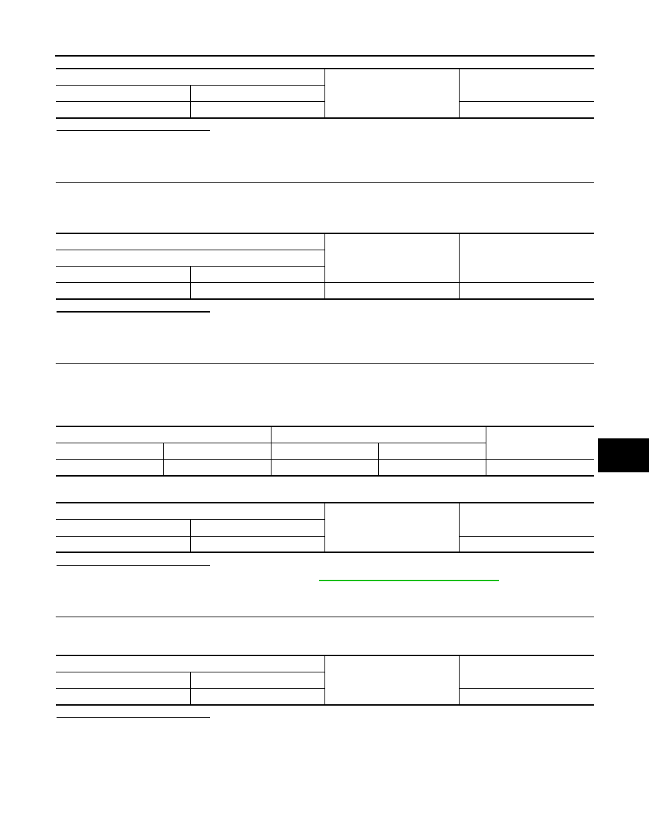
Check voltage between reclining motor harness connector and ground.

Is the inspection result normal?

YES

>> GO TO 5.

NO

>> GO TO 4.

4.

CHECK RECLINING SENSOR POWER SUPPLY CIRCUIT 

1.

Turn ignition switch OFF.

2.

Disconnect driver seat control unit connector.

3.

Check continuity between driver seat control unit harness connector and reclining motor harness connec-
tor.

4.

Check continuity between driver seat control unit harness connector and ground.

Is the inspection result normal?

YES

>> Replace driver seat control unit. Refer to 

ADP-121, "Removal and Installation"

.

NO

>> Repair or replace harness or connector.

5.

CHECK RECLINING SENSOR GROUND 

1.

Turn ignition switch OFF.

2.

Check continuity between reclining motor harness connector and ground.

Is the inspection result normal?

YES

>> Replace seat cushion frame assembly.

NO

>> Repair or replace harness or connector.

Driver seat control unit

Ground

Continuity 

Connector

Terminal

B452

20

Not existed

(+)

(–)

Voltage (V)

(Approx.)

Reclining motor

Connector

Terminals

B454

33

Ground

12

Driver seat control unit

Reclining motor

Continuity

Connector

Terminal

Connector

Terminal

B452

33

B454

33

Existed

Driver seat control unit

Ground

Continuity 

Connector

Terminal

B452

33

Not existed

Reclining motor

Ground

Continuity

Connector

Terminal

B454

46

Existed

Revision: 2012 October

2013 Murano CrossCabriolet

ADP-78

< DTC/CIRCUIT DIAGNOSIS >

LIFTING SENSOR (FRONT)

LIFTING SENSOR (FRONT)

Component Function Check

INFOID:0000000008463620

1.

CHECK FUNCTION

1.

Select “LIFT FR PULSE” in “Data monitor” mode with CONSULT.

2.

Check the lifting sensor (front) signal under the following conditions.

*: The value at the seat position attained when the battery is connected is considered to be 32768.

Is the indication normal?

YES

>> INSPECTION END

NO

>> Refer to 

ADP-78, "Diagnosis Procedure"

.

Diagnosis Procedure

INFOID:0000000008463621

1.

CHECK LIFTING SENSOR (FRONT) SIGNAL

1.

Turn ignition switch ON.

2.

Check signal driver seat control unit harness connector and ground using an oscilloscope.

Is the inspection result normal?

YES

>> Replace driver seat control unit. Refer to 

ADP-121, "Removal and Installation"

.

NO

>> GO TO 2.

2.

CHECK LIFTING SENSOR (FRONT) CIRCUIT

1.

Turn ignition switch OFF.

2.

Disconnect driver seat control unit and lifting motor (front) connector.

3.

Check continuity between driver seat control unit harness connector and lifting motor (front) harness con-
nector.

4.

Check continuity between driver seat control unit harness connector and ground.

Monitor item

Condition

Value

LIFT FR PULSE

Seat lifting (front)

Operate (up)

Change (increase)

*

Operate (down)

Change (decrease)

*

Release

No change

*

(+)

(–)

Condition

Voltage (V)

(Approx.)

Driver seat control unit

Connector

Terminals

B452

22

Ground

Seat Lifting
(front)

Operate

Other than 
above

0 or 5

JMJIA0119ZZ

Driver seat control unit

Lifting motor (front)

Continuity

Connector

Terminal

Connector

Terminal

B452

22

B455

22

Existed

Revision: 2012 October

2013 Murano CrossCabriolet

LIFTING SENSOR (FRONT)

ADP-79

< DTC/CIRCUIT DIAGNOSIS >

C

D

E

F

G

H

I

K

L

M

A

B

ADP

N

O

P

Is the inspection result normal?

YES

>> GO TO 3.

NO

>> Repair or replace harness or connector.

3.

CHECK LIFTING SENSOR (FRONT) POWER SUPPLY

1.

Connect driver seat control unit connector.

2.

Turn ignition switch ON.

3.

Check voltage between lifting motor (front) harness connector and ground.

Is the inspection result normal?

YES

>> GO TO 5.

NO

>> GO TO 4.

4.

CHECK LIFTING SENSOR (FRONT) POWER SUPPLY CIRCUIT 

1.

Turn ignition switch OFF.

2.

Disconnect driver seat control unit connector.

3.

Check continuity between driver seat control unit harness connector and lifting motor (front) harness con-
nector.

4.

Check continuity between driver seat control unit harness connector and ground.

Is the inspection result normal?

YES

>> Replace driver seat control unit. Refer to 

ADP-121, "Removal and Installation"

.

NO

>> Repair or replace harness or connector.

5.

CHECK LIFTING SENSOR (FRONT) GROUND 

1.

Turn ignition switch OFF.

2.

Check continuity between lifting motor (front) harness connector and ground.

Is the inspection result normal?

YES

>> Replace seat cushion frame assembly.

NO

>> Repair or replace harness or connector.

Driver seat control unit

Ground

Continuity 

Connector

Terminal

B452

22

Not existed

(+)

(–)

Voltage (V)

(Approx.)

Lifting motor (front)

Connector

Terminals

B455

33

Ground

12

Driver seat control unit

Lifting motor (front)

Continuity

Connector

Terminal

Connector

Terminal

B452

33

B455

33

Existed

Driver seat control unit

Ground

Continuity 

Connector

Terminal

B452

33

Not existed

Lifting motor (front)

Ground

Continuity

Connector

Terminal

B455

48

Existed

Revision: 2012 October

2013 Murano CrossCabriolet

ADP-80

< DTC/CIRCUIT DIAGNOSIS >

LIFTING SENSOR (REAR)

LIFTING SENSOR (REAR)

Component Function Check

INFOID:0000000008463622

1.

CHECK FUNCTION

1.

Select “LIFT RR PULSE” in “Data monitor” mode with CONSULT.

2.

Check lifting sensor (rear) signal under the following conditions.

*: The value at the seat position attained when the battery is connected is considered to be 32768.

Is the indication normal?

YES

>> INSPECTION END

NO

>> Refer to 

ADP-80, "Diagnosis Procedure"

.

Diagnosis Procedure

INFOID:0000000008463623

1.

CHECK LIFTING SENSOR (REAR) SIGNAL

1.

Turn ignition switch ON.

2.

Check signal between driver seat control unit harness connector and ground using an oscilloscope.

Is the inspection result normal?

YES

>> Replace driver seat control unit. Refer to 

ADP-121, "Removal and Installation"

.

NO

>> GO TO 2.

2.

CHECK LIFTING SENSOR (REAR) CIRCUIT

1.

Turn ignition switch OFF.

2.

Disconnect driver seat control unit and lifting motor (rear) connector.

3.

Check the continuity between driver seat control unit harness connector and lifting motor (rear) harness
connector.

4.

Check the continuity between driver seat control unit harness connector and ground.

Monitor item

Condition

Value

LIFT RR PULSE

Seat lifting (rear)

Operate (up)

Change (increase)

*

Operate (down)

Change (decrease)

*

Release

No change

*

(+)

(–)

Condition

Voltage (V)

(Approx.)

Driver seat control unit

Connector

Terminals

B452

21

Ground

Seat Lifting
(rear)

Operate

Other than 
above

0 or 5

JMJIA0119ZZ

Driver seat control unit

Lifting motor (rear)

Continuity

Connector

Terminal

Connector

Terminal

B452

21

B456

21

Existed

Revision: 2012 October

2013 Murano CrossCabriolet

LIFTING SENSOR (REAR)

ADP-81

< DTC/CIRCUIT DIAGNOSIS >

C

D

E

F

G

H

I

K

L

M

A

B

ADP

N

O

P

Is the inspection result normal?

YES

>> GO TO 3.

NO

>> Repair or replace harness or connector.

3.

CHECK LIFTING SENSOR (REAR) POWER SUPPLY

1.

Connect driver seat control unit connector.

2.

Turn ignition switch ON.

3.

Check the voltage between lifting motor (rear) harness connector and ground.

Is the inspection result normal?

YES

>> GO TO 5.

NO

>> GO TO 4.

4.

CHECK LIFTING SENSOR (REAR) POWER SUPPLY CIRCUIT 

1.

Turn ignition switch OFF.

2.

Disconnect driver seat control unit connector.

3.

Check the continuity between driver seat control unit harness connector and lifting motor (rear) harness
connector.

4.

Check the continuity between driver seat control unit harness connector and ground.

Is the inspection result normal?

YES

>> Replace driver seat control unit. Refer to 

ADP-121, "Removal and Installation"

.

NO

>> Repair or replace harness or connector.

5.

CHECK LIFTING SENSOR (REAR) GROUND 

1.

Turn ignition switch OFF.

2.

Check the continuity between lifting motor (rear) harness connector and ground.

Is the inspection result normal?

YES

>> Replace seat cushion frame assembly.

NO

>> Repair or replace harness or connector.

Driver seat control unit

Ground

Continuity 

Connector

Terminal

B452

21

Not existed

(+)

(–)

Voltage (V)

(Approx.)

Lifting motor (rear)

Connector

Terminals

B456

33

Ground

12

Driver seat control unit

Lifting motor (rear)

Continuity

Connector

Terminal

Connector

Terminal

B452

33

B456

33

Existed

Driver seat control unit

Ground

Continuity 

Connector

Terminal

B452

33

Not existed

Lifting motor (rear)

Ground

Continuity

Connector

Terminal

B456

47

Existed

Revision: 2012 October

2013 Murano CrossCabriolet

ADP-82

< DTC/CIRCUIT DIAGNOSIS >

TILT SENSOR

TILT SENSOR

Component Function Check

INFOID:0000000008463624

1.

CHECK FUNCTION

1.

Select “TILT PULSE” in “Data monitor” mode with CONSULT.

2.

Check tilt sensor signal under the following conditions.

*: The value at the seat position attained when the battery is connected is considered to be 32768.

Is the indication normal?

YES

>> INSPECTION END

NO

>> Refer to 

ADP-82, "Diagnosis Procedure"

.

Diagnosis Procedure

INFOID:0000000008463625

1.

CHECK TILT SENSOR SIGNAL

1.

Turn ignition switch ON.

2.

Check signal between driver seat control unit harness connector and ground using an oscilloscope. 

Is the inspection result normal?

YES

>> Replace driver seat control unit. Refer to 

ADP-121, "Removal and Installation"

.

NO

>> GO TO 2.

2.

CHECK TILT SENSOR CIRCUIT

1.

Turn ignition switch OFF.

2.

Disconnect driver seat control unit and tilt motor connector.

3.

Check continuity between driver seat control unit harness connector and tilt motor harness connector.

4.

Check continuity between driver seat control unit harness connector and ground.

Monitor item

Condition

Value

TILT PULSE

Steering column

Operate (up)

Change (increase)*

Operate (down)

Change (decrease)

*

Release

No change*

(+)

(–)

Condition

Voltage (V)

(Approx.)

Driver seat control unit

Connector

Terminals

B452

30

Ground

Steering column

Operate

Other than 
above

0 or 5

JMJIA0119ZZ

Driver seat control unit

Tilt motor

Continuity

Connector

Terminal

Connector

Terminal

B452

30

M116

5

Existed

Driver seat control unit

Ground

Continuity 

Connector

Terminal

B452

30

Not existed

Revision: 2012 October

2013 Murano CrossCabriolet

TILT SENSOR

ADP-83

< DTC/CIRCUIT DIAGNOSIS >

C

D

E

F

G

H

I

K

L

M

A

B

ADP

N

O

P

Is the inspection result normal?

YES

>> GO TO 3.

NO

>> Repair or replace harness or connector.

3.

CHECK TILT SENSOR POWER SUPPLY

1.

Turn ignition switch ON.

2.

Check voltage between tilt motor harness connector and ground.

Is the inspection result normal?

YES

>> GO TO 5.

NO

>> GO TO 4.

4.

CHECK TILT SENSOR POWER SUPPLY CIRCUIT 

1.

Turn ignition switch OFF.

2.

Disconnect automatic drive positioner control unit connector.

3.

Check continuity between automatic drive positioner control unit harness connector and tilt motor harness
connector.

4.

Check continuity between automatic drive positioner control unit harness connector and ground.

Is the inspection result normal?

YES

>> Replace automatic drive positioner control unit. Refer to 

ADP-122, "Removal and Installation"

.

NO

>> Repair or replace harness or connector.

5.

CHECK TILT SENSOR GROUND CIRCUIT

1.

Turn ignition switch OFF.

2.

Disconnect automatic drive positioner control unit connector.

3.

Check continuity between automatic drive positioner control unit harness connector and tilt motor harness
connector.

4.

Check continuity between automatic drive positioner control unit harness connector and ground.

Is the inspection result normal?

YES

>> Replace tilt motor.

NO

>> Repair or replace harness or connector.

(+)

(–)

Voltage (V)

(Approx.)

Tilt motor

Connector

Terminals

M116

4

Ground

12

Automatic drive positioner control unit

Tilt motor

Continuity

Connector

Terminal

Connector

Terminal

M104

27

M116

4

Existed

Automatic drive positioner control unit

Ground

Continuity 

Connector

Terminal

M104

27

Not existed

Automatic drive positioner control unit

Tilt motor

Continuity

Connector

Terminal

Connector

Terminal

M75

20

M116

6

Existed

Automatic drive positioner control unit

Ground

Continuity

Connector

Terminal

M75

20

Not existed

Revision: 2012 October

2013 Murano CrossCabriolet

ADP-84

< DTC/CIRCUIT DIAGNOSIS >

TELESCOPIC SENSOR

TELESCOPIC SENSOR

Component Function Check

INFOID:0000000008463626

1.

CHECK FUNCTION

1.

Select “TELESCO PULSE” in “Data monitor” mode with CONSULT.

2.

Check telescopic sensor signal under the following conditions.

*: The value at the seat position attained when the battery is connected is considered to be 32768.

Is the indication normal?

YES

>> INSPECTION END

NO

>> Refer to 

ADP-84, "Diagnosis Procedure"

.

Diagnosis Procedure

INFOID:0000000008463627

1.

CHECK TELESCOPIC SENSOR SIGNAL

1.

Turn ignition switch ON.

2.

Check signal between driver seat control unit harness connector and ground using an oscilloscope. 

Is the inspection result normal?

YES

>> Replace driver seat control unit. Refer to 

ADP-121, "Removal and Installation"

.

NO

>> GO TO 2.

2.

CHECK TELESCOPIC SENSOR CIRCUIT

1.

Turn ignition switch OFF.

2.

Disconnect driver seat control unit and telescopic motor connector.

3.

Check continuity between driver seat control unit harness connector and telescopic motor harness con-
nector.

4.

Check continuity between driver seat control unit harness connector and ground.

Monitor item

Condition

Valve

TELESCO PULSE

Steering column

Operate (forward)

Change (increase)

*

Operate (backward)

Change (decrease)

*

Release

No change

*

(+)

(–)

Condition

Voltage (V)

(Approx.)

Driver seat control unit

Connector

Terminals

B452

31

Ground

Steering column

Operate

Other than 
above

0 or 5

JMJIA0119ZZ

Driver seat control unit

Telescopic motor

Continuity

Connector

Terminal

Connector

Terminal

B452

31

M117

5

Existed

Revision: 2012 October

2013 Murano CrossCabriolet

TELESCOPIC SENSOR

ADP-85

< DTC/CIRCUIT DIAGNOSIS >

C

D

E

F

G

H

I

K

L

M

A

B

ADP

N

O

P

Is the inspection result normal?

YES

>> GO TO 3.

NO

>> Repair or replace harness or connector.

3.

CHECK TELESCOPIC SENSOR POWER SUPPLY

1.

Turn ignition switch ON.

2.

Check voltage between telescopic motor harness connector and ground.

Is the inspection result normal?

YES

>> GO TO 5.

NO

>> GO TO 4.

4.

CHECK TELESCOPIC SENSOR POWER SUPPLY CIRCUIT 

1.

Turn ignition switch OFF.

2.

Disconnect automatic drive positioner control unit connector.

3.

Check continuity between automatic drive positioner control unit harness connector and telescopic motor
harness connector.

4.

Check continuity between automatic drive positioner control unit harness connector and ground.

Is the inspection result normal?

YES

>> Replace automatic drive positioner control unit. Refer to 

ADP-122, "Removal and Installation"

.

NO

>> Repair or replace harness or connector.

5.

CHECK TELESCOPIC SENSOR GROUND CIRCUIT

1.

Turn ignition switch OFF.

2.

Disconnect automatic drive positioner control unit connector.

3.

Check continuity between automatic drive positioner control unit harness connector and telescopic motor
harness connector.

4.

Check continuity between automatic drive positioner control unit harness connector and ground.

Is the inspection result normal?

Driver seat control unit

Ground

Continuity 

Connector

Terminal

B452

31

Not existed

(+)

(–)

Voltage (V)

(Approx.)

Telescopic motor

Connector

Terminals

M117

4

Ground

12

Automatic drive positioner control unit

Telescopic motor

Continuity

Connector

Terminal

Connector

Terminal

M104

27

M117

4

Existed

Automatic drive positioner control unit

Ground

Continuity 

Connector

Terminal

M104

27

Not existed

Automatic drive positioner control unit

Telescopic motor

Continuity

Connector

Terminal

Connector

Terminal

M75

20

M117

6

Existed

Automatic drive positioner control unit

Ground

Continuity 

Connector

Terminal

M75

20

Not existed

Revision: 2012 October

2013 Murano CrossCabriolet

ADP-86

< DTC/CIRCUIT DIAGNOSIS >

TELESCOPIC SENSOR

YES

>> Replace telescopic motor.

NO

>> Repair or replace harness or connector.

Revision: 2012 October

2013 Murano CrossCabriolet

MIRROR SENSOR

ADP-87

< DTC/CIRCUIT DIAGNOSIS >

C

D

E

F

G

H

I

K

L

M

A

B

ADP

N

O

P

MIRROR SENSOR

DRIVER SIDE

DRIVER SIDE : Component Function Check

INFOID:0000000008463628

1.

CHECK FUNCTION

1.

Select “MIR/SEN LH U-D”, “MIR/SEN LH R-L” in “Data monitor” with CONSULT.

2.

Check mirror sensor (driver side) signal under the following condition.

Is the indication normal?

YES

>> INSPECTION END

NO

>> Refer to 

ADP-87, "DRIVER SIDE : Diagnosis Procedure"

.

DRIVER SIDE : Diagnosis Procedure

INFOID:0000000008463629

1.

CHECK DOOR MIRROR (DRIVER SIDE) SENSOR POWER SUPPLY

1.

Turn ignition switch OFF.

2.

Disconnect door mirror (driver side) connector.

3.

Turn ignition switch ON.

4.

Check voltage between door mirror (driver side) harness connector and ground.

Is the inspection result normal?

YES

>> GO TO 3.

NO

>> GO TO 2.

2.

CHECK DOOR MIRROR (DRIVER SIDE) SENSOR POWER SUPPLY CIRCUIT 

1.

Turn ignition switch OFF.

2.

Disconnect automatic drive positioner control unit connector.

3.

Check continuity between automatic drive positioner control unit harness connector and door mirror
(driver side) harness connector.

4.

Check continuity between automatic drive positioner control unit harness connector and ground.

Is the inspection result normal?

YES

>> Replace automatic drive positioner control unit. Refer to 

ADP-122, "Removal and Installation"

.

NO

>> Repair or replace harness or connector.

Monitor item

Condition

Value

MIR/SEN LH U-D

Door mirror (driver side)

Change between 

3.4 [V] (close to peak)

0.6 [V] (close to valley)

MIR/SEN LH R-L

Change between 

0.6 [V] (close to left edge)

3.4 [V] (close to right edge)

(+)

(–)

Voltage (V)

(Approx.)

Door mirror (driver side)

Connector

Terminals

D3

23

Ground

5

Automatic drive positioner control unit

Door mirror (driver side)

Continuity

Connector

Terminal

Connector

Terminal

M75

21

D3

23

Existed

Automatic drive positioner control unit

Ground

Continuity 

Connector

Terminal

M75

21

Not existed

Revision: 2012 October

2013 Murano CrossCabriolet

ADP-88

< DTC/CIRCUIT DIAGNOSIS >

MIRROR SENSOR

3.

CHECK DOOR MIRROR (DRIVER SIDE) SENSOR GROUND 

1.

Turn ignition switch OFF.

2.

Disconnect automatic drive positioner control unit connector.

3.

Check continuity between automatic drive positioner control unit harness connector and door mirror
(driver side) harness connector.

4.

Check continuity between automatic drive positioner control unit harness connector and ground.

Is the inspection result normal?

YES

>> GO TO 4.

NO

>> Repair or replace harness or connector.

4.

CHECK DOOR MIRROR (DRIVER SIDE) SENSOR CIRCUIT

1.

Check continuity between automatic drive positioner control unit harness connector and door mirror
(driver side) harness connector.

2.

Check continuity between automatic drive positioner control unit harness connector and ground.

Is the inspection result normal?

YES

>> Replace door mirror (driver side).

NO

>> Repair or replace harness or connector.

PASSENGER SIDE

PASSENGER SIDE : Component Function Check

INFOID:0000000008463630

1.

CHECK FUNCTION

1.

Select “MIR/SEN RH U-D”, “MIR/SEN RH R-L” in “Data monitor” with CONSULT.

2.

Check the mirror sensor (passenger side) signal under the following conditions.

Is the indication normal?

YES

>> INSPECTION END

Automatic drive positioner control unit

Door mirror (driver side)

Continuity

Connector

Terminal

Connector

Terminal

M75

20

D3

24

Existed

Automatic drive positioner control unit

Ground

Continuity

Connector

Terminal

M75

20

Not existed

Automatic drive positioner control unit

Door mirror (driver side)

Continuity

Connector

Terminal

Connector

Terminal

M75

6

D3

21

Existed

18

22

Automatic drive positioner control unit

Ground

Continuity 

Connector

Terminal

M75

6

Not existed

18

Monitor item

Condition

Value

MIR/SEN RH U-D

Door mirror (passenger side)

Change between 

3.4 [V] (close to peak)

0.6 [V] (close to valley)

MIR/SEN RH R-L

Change between 

3.4 [V] (close to left edge)

0.6 [V] (close to right edge)

Revision: 2012 October

2013 Murano CrossCabriolet

MIRROR SENSOR

ADP-89

< DTC/CIRCUIT DIAGNOSIS >

C

D

E

F

G

H

I

K

L

M

A

B

ADP

N

O

P

NO

>> Refer to 

ADP-89, "PASSENGER SIDE : Diagnosis Procedure"

.

PASSENGER SIDE : Diagnosis Procedure

INFOID:0000000008463631

1.

CHECK DOOR MIRROR SENSOR (PASSENGER SIDE) POWER SUPPLY

1.

Turn ignition switch OFF.

2.

Disconnect door mirror (passenger side) connector.

3.

Turn ignition switch ON.

4.

Check voltage between door mirror (passenger side) harness connector and ground.

Is the inspection result normal?

YES

>> GO TO 3.

NO

>> GO TO 2.

2.

CHECK DOOR MIRROR (PASSENGER SIDE) SENSOR POWER SUPPLY CIRCUIT 

1.

Turn ignition switch OFF.

2.

Disconnect automatic drive positioner control unit connector.

3.

Check continuity between automatic drive positioner control unit harness connector and door mirror (pas-
senger side) harness connector.

4.

Check continuity between automatic drive positioner control unit harness connector and ground.

Is the inspection result normal?

YES

>> Replace automatic drive positioner control unit. Refer to 

ADP-122, "Removal and Installation"

.

NO

>> Repair or replace harness or connector.

3.

CHECK DOOR MIRROR (PASSENGER SIDE) SENSOR GROUND 

1.

Turn ignition switch OFF.

2.

Disconnect automatic drive positioner control unit connector.

3.

Check continuity between automatic drive positioner control unit harness connector and door mirror (pas-
senger side) connector.

4.

Check continuity between automatic drive positioner control unit harness connector and ground.

Is the inspection result normal?

YES

>> GO TO 4.

NO

>> Repair or replace harness or connector.

(+)

(–)

Voltage (V)

(Approx.)

Door mirror (passenger side)

Connector

Terminals

D43

23

Ground

5

Automatic drive positioner control unit

Door mirror (passenger side)

Continuity

Connector

Terminal

Connector

Terminal

M75

21

D43

23

Existed

Automatic drive positioner control unit

Ground

Continuity 

Connector

Terminal

M75

21

Not existed

Automatic drive positioner control unit

Door mirror (passenger side)

Continuity

Connector

Terminal

Connector

Terminal

M75

20

D43

24

Existed

Automatic drive positioner control unit

Ground

Continuity 

Connector

Terminal

M75

20

Not existed

Revision: 2012 October

2013 Murano CrossCabriolet

ADP-90

< DTC/CIRCUIT DIAGNOSIS >

MIRROR SENSOR

4.

CHECK DOOR MIRROR (PASSENGER SIDE) SENSOR HARNESS CONTINUITY

1.

Turn ignition switch OFF.

2.

Disconnect automatic drive positioner control unit and door mirror (passenger side) connector.

3.

Check continuity between automatic drive positioner control unit harness connector and door mirror (pas-
senger side) harness connector.

4.

Check continuity between automatic drive positioner control unit harness connector and ground.

Is the inspection result normal?

YES

>> Replace door mirror (passenger side).

NO

>> Repair or replace harness or connector.

Automatic drive positioner control unit

Door mirror (passenger side)

Continuity

Connector

Terminal

Connector

Terminal

M75

5

D43

21

Existed

17

22

Automatic drive positioner control unit

Ground

Continuity 

Connector

Terminal

M75

5

Not existed

17

Revision: 2012 October

2013 Murano CrossCabriolet

SLIDING MOTOR

ADP-91

< DTC/CIRCUIT DIAGNOSIS >

C

D

E

F

G

H

I

K

L

M

A

B

ADP

N

O

P

SLIDING MOTOR

Component Function Check

INFOID:0000000008463632

1.

CHECK FUNCTION

1.

Select “SEAT SLIDE” in “Active test” mode with CONSULT.

2.

Check the sliding motor operation.

Is the operation of relevant parts normal?

YES

>> INSPECTION END

NO

>> Refer to 

ADP-91, "Diagnosis Procedure"

.

Diagnosis Procedure

INFOID:0000000008463633

1.

CHECK SLIDING MOTOR INPUT SIGNAL

1.

Turn ignition switch OFF.

2.

Disconnect sliding motor connector.

3.

Turn the ignition switch ON.

4.

Perform “Active test” (“SEAT SLIDE”) with CONSULT.

5.

Check voltage between sliding motor harness connector and ground.

Is the inspection result normal?

YES

>> Replace seat cushion frame assembly.

NO

>> GO TO 2.

2.

CHECK SLIDING MOTOR CIRCUIT

1.

Turn ignition switch OFF.

2.

Disconnect driver seat control unit connector.

3.

Check continuity between driver seat control unit harness connector and sliding motor harness connector.

4.

Check continuity between driver seat control unit harness connector and ground.

Test item

Description

SEAT SLIDE

OFF

Seat sliding

Stop

FR

Forward

RR

Backward

(+)

(–)

Condition

Voltage (V)

(Approx.)

Sliding motor

Connector

Terminals

B461

50

Ground

SEAT SLIDE

OFF

0

Forward

0

Backward

12

51

OFF

0

Forward

12

Backward

0

Driver seat control unit

Sliding motor

Continuity

Connector

Terminal

Connector

Terminal

B451

3

B461

50

Existed

4

51

Revision: 2012 October

2013 Murano CrossCabriolet

ADP-92

< DTC/CIRCUIT DIAGNOSIS >

SLIDING MOTOR

Is the inspection result normal?

YES

>> Replace driver seat control unit. Refer to 

ADP-121, "Removal and Installation"

.

NO

>> Repair or replace harness or connector.

Driver seat control unit

Ground

Continuity 

Connector

Terminal

B451

3

Not existed

4

Revision: 2012 October

2013 Murano CrossCabriolet


Content      ..     4      5      6      7     ..