Nissan Murano Z51 (2012 year). Manual - part 82
DIAGNOSIS SENSOR UNIT
SR-53
< REMOVAL AND INSTALLATION >
[FOR MEXICO]
C
D
E
F
G
I
J
K
L
M
A
B
SR
N
O
P
DIAGNOSIS SENSOR UNIT
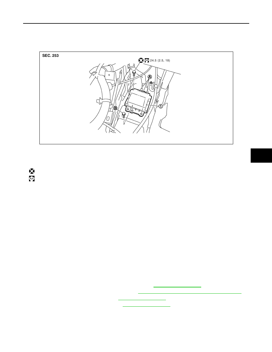
Exploded View
INFOID:0000000007539702
Removal and Installation
INFOID:0000000007539703
WARNING:
• Before servicing, turn ignition switch OFF, disconnect battery negative terminal and wait 3 minutes
or more.
• Before disconnecting the air bag sensor unit harness connector, be sure to disconnect the each har-
ness connector of the air bag module and pre-tensioner seat belt to prevent air bag deployment by
static electricity and pre-tensioner seat belt operation.
• Never use the air tools or electric tools for servicing.
• When replacing the air bag diagnosis sensor unit, always check with the parts department for the lat-
est parts information. Installing an incorrect air bag diagnosis sensor unit may or may not cause the
air bag warning lamp to illuminate and may cause incorrect deployment of the supplemental air bags
and seat belt pre-tensioners in a collision resulting in serious personal injury or death.
REMOVAL
1.
Always check the air bag diagnosis sensor unit ECU discriminated number (identification number) using
CONSULT.
2.
Disconnect the each connector of all air bag modules and pre-tensioner seat belts.
3.
Remove the instrument lower cover (LH and RH). Refer to
.
4.
Remove the rear foot duct 1 (LH and RH). Refer to
VTL-125, "REAR FOOT DUCT 1 : Exploded View"
.
5.
Remove the instrument stay LH. Refer to
6.
Remove the front console bracket. Refer to
7.
Disconnect the diagnosis sensor unit harness connectors.
8.
Remove the fixing bolts, ground bolt, and then remove the diagnosis sensor unit.
CAUTION:
1.
Diagnosis sensor unit
A.
Diagnosis sensor unit harness connector
B.
Ground bolt
: Do not reuse
: N·m (kg-m, ft-lb)
JMHIA0517GB
Revision: 2013 February
2012 MURANO