Nissan Murano Z51 (2011 year). Manual - part 58


  Index      Manuals     Nissan Murano Z51 (2011 year) - Service and Repair Manual


Search            copyright infringement  


Content      ..     56      57      58      59     ..


Nissan Murano Z51 (2011 year). Manual - part 58


HYDRAULIC LINE

ST-109

< REMOVAL AND INSTALLATION >

[WITHOUT HEATED STEERING WHEEL]

C

D

E

F

H

I

J

K

L

M

A

B

ST

N

O

P

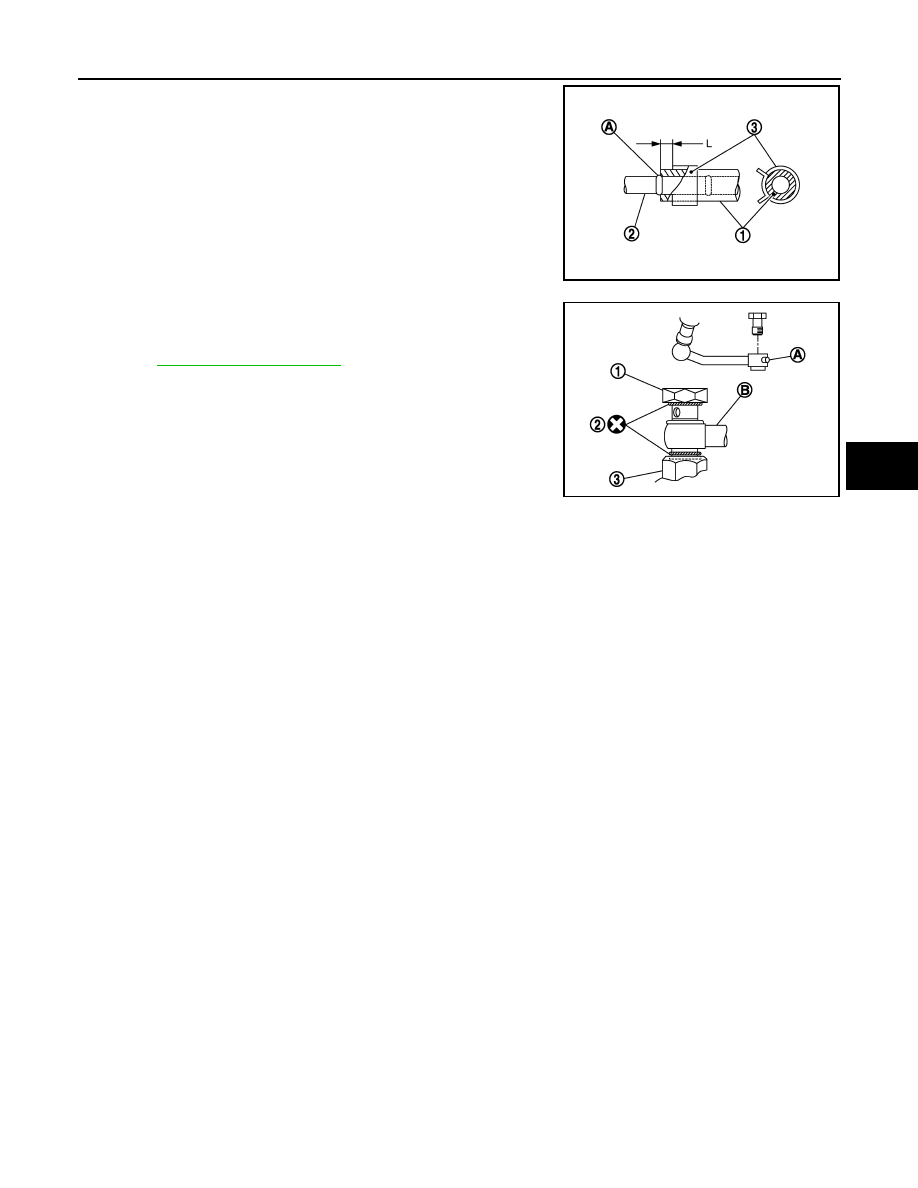
• Never apply fluid to the hose (1) and tube (2).
• Insert hose securely until it contacts spool (A) of tube.
• Leave clearance (L) when installing clamp (3).

• Install eye bolt with eye joint (assembled to high pressure

hose) (B) protrusion (A) facing with pump side cutout, and
then tighten it to the specified torque after tightening by hand.
Refer to 

ST-108, "Exploded View"

.

• Securely insert harness connector to pressure sensor.
• Apply power steering fluid to around copper washer, then

install eye bolt.

• Never reuse copper washer.

Standard

L

: 3 – 8 mm (0.12 – 0.31 in)

JSGIA0118ZZ

SGIA1379E

Revision: 2011 November

2011 MURANO

ST-110

< SERVICE DATA AND SPECIFICATIONS (SDS) 

[WITHOUT HEATED STEERING WHEEL]

SERVICE DATA AND SPECIFICATIONS (SDS)

SERVICE DATA AND SPECIFICATIONS (SDS)

SERVICE DATA AND SPECIFICATIONS (SDS)

General Specifications

INFOID:0000000006843255

Steering Wheel Axial End Play and Play

INFOID:0000000006843256

Unit: mm (in)

Steering Wheel Turning Force

INFOID:0000000006843257

Unit: N·m (kg-m, in-lb)

Steering Angle

INFOID:0000000006843258

Unit: Degree minute (Decimal degree)

Steering Column Length

INFOID:0000000006843259

Unit: mm (in)

Steering Column Mounting Dimensions

INFOID:0000000006843260

Unit: mm (in)

Steering Column Operating Range

INFOID:0000000006843261

Steering gear model

PR26AF

Fluid capacity (Approx.)

 (US qt, lmp qt)

1.0 (1-1/8, 7/8)

Item

Standard

Steering wheel axial end play

0 (0)

Steering wheel play on the outer circumference

0 – 35 (0 – 1.38)

Item

Standard

Steering wheel turning force

7.45 (0.76, 66)

Item

Standard

Wheel size: 18 inch

Wheel size: 20 inch

Inner wheel

Minimum

33

°

30

 (33.5

°

)

32

°

00

 (32.0

°

)

Nominal

36

°

30

 (36.5

°

)

35

°

00

 (35.0

°

)

Maximum

37

°

30

 (37.5

°

)

36

°′

 (36.0

°

)

Outer wheel

Nominal

31

°

30

 (31.5

°

)

30

°

30

 (30.5

°

)

Item

Standard

Column length

463 (18.23)

Item

Standard

Mounting dimension

30 (1.18) or less

Item

Standard

Without electric motor

With electric motor

Tilt operating range 

15

°

18

°

Telescopic operating range 

40 mm (1.57 in)

Rotating torque

0.49 N·m (0.05 kg-m, 4 in-lb)

Revision: 2011 November

2011 MURANO

SERVICE DATA AND SPECIFICATIONS (SDS)

ST-111

< SERVICE DATA AND SPECIFICATIONS (SDS) 

[WITHOUT HEATED STEERING WHEEL]

C

D

E

F

H

I

J

K

L

M

A

B

ST

N

O

P

Lower Shaft Length

INFOID:0000000006843262

Unit: mm (in)

Rack Sliding Force

INFOID:0000000006843263

Unit: N (kg, lb)

Rack Stroke

INFOID:0000000006843264

Unit: mm (in)

Socket Swing Force and Rotating Torque

INFOID:0000000006843265

SWING FORCE

Unit: N (kg, lb)

ROTATING TORQUE

Unit: N·m (kg-m, in-lb)

Socket Axial End Play

INFOID:0000000006843266

Unit: mm (in)

Inner Socket Length

INFOID:0000000006843267

Unit: mm (in)

Relief Oil Pressure

INFOID:0000000006843268

Unit: kPa (kg/cm

2

, psi)

Item

Standard

Lower shaft length

160 (6.3) or more

Item

Standard

2WD

AWD

Rack sliding force

195 – 258 (19.9 – 26.3, 43.8 – 

57.9)

227 – 305 (23.2 – 31.1, 51.1 – 

68.5)

Item

Standard

Wheel size: 18 inch

Wheel size: 20 inch

Rack neutral position 

70.5 (2.776)

68.0 (2.677)

Item

Standard

Outer socket

4.81 – 45.7 (0.5 – 4.6, 1.1 – 10.2)

Inner socket

8.9 – 64 (0.91 – 6.5, 2.01 – 14.3)

Item

Standard

Outer socket 

0.3 – 2.9 (0.03 – 0.29, 3 – 25)

Item

Standard

Outer socket

0.5 (0.02) or less

Inner socket

0.2 (0.008) or less

Item

Standard

Rack neutral position

120.3 (4.74)

Item

Standard

Relief oil pressure

9,500 – 10,300 (96.9 – 105.1, 1,378 – 1,494)

Revision: 2011 November

2011 MURANO

STC-1

STEERING

C

D

E

F

H

I

J

K

L

M

SECTION 

STC

A

B

STC

N

O

P

CONTENTS

STEERING CONTROL SYSTEM

BASIC INSPECTION  ....................................

2

DIAGNOSIS AND REPAIR WORK FLOW  .........

2

Work Flow  .................................................................

2

SYSTEM DESCRIPTION  ..............................

3

EPS SYSTEM  ......................................................

3

System Diagram ........................................................

3

System Description  ...................................................

3

Component Parts Location ........................................

5

Component Description .............................................

5

DTC/CIRCUIT DIAGNOSIS  ..........................

6

POWER SUPPLY AND GROUND CIRCUIT .......

6

Description ................................................................

6

Diagnosis Procedure .................................................

6

POWER STEERING SOLENOID VALVE  ...........

7

Description ................................................................

7

Diagnosis Procedure .................................................

7

Component Inspection  ..............................................

8

ENGINE SPEED SIGNAL CIRCUIT  ....................

9

Description ................................................................

9

Diagnosis Procedure .................................................

9

VEHICLE SPEED SIGNAL CIRCUIT  .................

11

Description ..............................................................

11

Diagnosis Procedure ...............................................

11

ECU DIAGNOSIS INFORMATION ..............

13

POWER STEERING CONTROL UNIT ..............

13

Reference Value ......................................................

13

Wiring Diagram - ELECTRONICALLY CON-
TROLLED POWER STEERING SYSTEM -  ............

15

Fail-Safe ..................................................................

17

SYMPTOM DIAGNOSIS  ..............................

19

UNBALANCE STEERING WHEEL TURNING 
FORCE (TORQUE VARIATION) .......................

19

Description ...............................................................

19

Diagnosis Procedure  ...............................................

19

PRECAUTION ..............................................

20

PRECAUTIONS .................................................

20

FOR USA AND CANADA  ..........................................

20

FOR USA AND CANADA : Precaution for Supple-
mental Restraint System (SRS) "AIR BAG" and 
"SEAT BELT PRE-TENSIONER" ............................

20

FOR MEXICO .............................................................

20

FOR MEXICO : Precaution for Supplemental Re-
straint System (SRS) "AIR BAG" and "SEAT BELT 
PRE-TENSIONER" ..................................................

20

REMOVAL AND INSTALLATION  ...............

22

POWER STEERING CONTROL UNIT ..............

22

Removal and Installation  .........................................

22

Revision: 2011 November

2011 MURANO

STC-2

< BASIC INSPECTION >

DIAGNOSIS AND REPAIR WORK FLOW

BASIC INSPECTION

DIAGNOSIS AND REPAIR WORK FLOW

Work Flow

INFOID:0000000006257944

DETAILED FLOW

1.

COLLECT THE INFORMATION FROM THE CUSTOMER

It is also important to clarify customer complaints before inspection. First of all, reproduce symptoms and
understand them fully. Ask customer about his/her complaints carefully. In some cases, it is necessary to
check symptoms by driving vehicle with customer.

CAUTION:

Customers are not professional. It is dangerous to make an easy guess like “maybe the customer
means that...,” or “maybe the customer mentions this symptom”.

>> GO TO 2.

2.

CHECK THE STATUS

1.

Power steering fluid leakage and check the power steering fluid level. Refer to 

ST-31, "Inspection"

 (With

heated steering wheel), 

ST-77, "Inspection"

 (Without heated steering wheel).

2.

Check the drive belt tension. Refer to 

EM-17, "Checking"

.

3.

Check the power steering gear for damages, cracks and fluid leakage. Refer to 

ST-31, "Inspection"

 (With

heated steering wheel), 

ST-77, "Inspection"

 (Without heated steering wheel).

4.

Check the relief oil pressure. Refer to 

ST-60, "Inspection"

 (With heated steering wheel), 

ST-106, "Inspec-

tion"

 (Without heated steering wheel).

>> GO TO 3.

3.

DIAGNOSIS CHART BY SYMPTOM

Perform the diagnosis by symptom. Refer to 

STC-19, "Diagnosis Procedure"

.

>> GO TO 4.

4.

FINAL CHECK

Check the input/output standard values for the power steering control unit.
Are the power steering control unit input/output values within standard ranges respectively?

YES

>> INSPECTION END

NO

>> GO TO 2.

Revision: 2011 November

2011 MURANO

EPS SYSTEM

STC-3

< SYSTEM DESCRIPTION >

C

D

E

F

H

I

J

K

L

M

A

B

STC

N

O

P

SYSTEM DESCRIPTION

EPS SYSTEM

System Diagram

INFOID:0000000006257945

CONTROL DIAGRAM

CROSS-SECTIONAL VIEW

System Description

INFOID:0000000006257946

• The EPS system controls the power steering solenoid valve through the power steering control unit.

JSGIA0119GB

1.

Combination meter

2.

Power steering control unit

3.

Power steering solenoid valve

4.

Steering gear assembly

5.

Gear housing assembly

6.

Gear sub-assembly

7.

Pinion

8.

Power steering oil pump

9.

Reservoir tank

JSGIA0376ZZ

Revision: 2011 November

2011 MURANO

STC-4

< SYSTEM DESCRIPTION >

EPS SYSTEM

• The valve driving voltage to control the power steering solenoid

valve varies according to the vehicle speed.

OPERATION PRINCIPLE

During Parking (When Turning The Steering Wheel To The Right.)

1.

Power steering solenoid valve is closed while a vehicle is stopped.

2.

Pinion “1R”, “2R” and “3R” are closed depending on steering torque of steering wheel.

3.

Oil pressure “P” in the gear housing assembly is the sum of oil pressures occurred in “2R” and “3R”. This
results in a light steering force because of high pressure.

During High-speed Operation

1.

Power steering solenoid valve is opened during high-speed operation.

2.

Pinion “1R”, “2R” and “3R” are closed depending on steering torque of steering wheel.

3.

Oil pressure “2R” does not occur because the power steering solenoid valve is on full throttle.

4.

Oil pressure “P” in the gear housing assembly includes only oil pressure occurred in “3R” and results in a
heavy steering force.

JSGIA0374GB

JSGIA0020GB

JSGIA0021GB

Revision: 2011 November

2011 MURANO

EPS SYSTEM

STC-5

< SYSTEM DESCRIPTION >

C

D

E

F

H

I

J

K

L

M

A

B

STC

N

O

P

Component Parts Location

INFOID:0000000006257947

Component Description

INFOID:0000000006257948

1.

Power steering solenoid valve

2.

Power steering control unit

A.

Steering gear assembly

B.

Glove box assembly removed

: Vehicle front

JSGIA0301ZZ

Component parts

Reference/Function

Power steering control unit

• Signals from various sensors control the driving voltage to the power steering solenoid valve.
• The power steering control unit controls the driving voltage to the power steering solenoid valve 

for maintaining the power steering assist force when the fail-safe function is activated. (The en-
gine speed signals control EPS system if any vehicle speed signal error is detected.)

Combination meter

STC-11, "Description"

ECM

STC-9, "Description"

Power steering solenoid valve

STC-7, "Description"

Revision: 2011 November

2011 MURANO

STC-6

< DTC/CIRCUIT DIAGNOSIS >

POWER SUPPLY AND GROUND CIRCUIT

DTC/CIRCUIT DIAGNOSIS

POWER SUPPLY AND GROUND CIRCUIT

Description

INFOID:0000000006257949

Power supply to EPS system

Diagnosis Procedure

INFOID:0000000006257950

1.

CHECK POWER SUPPLY

1.

Turn the ignition switch OFF.

2.

Disconnect power steering control unit harness connector.

3.

Check voltage between power steering control unit harness connector and ground.

4.

Turn the ignition switch ON.

CAUTION:

Never start the engine.

5.

Check voltage between power steering control unit harness connector and ground.

Is the inspection result normal?

YES

>> GO TO 2.

NO

>>

Check the following. If any items are damaged, repair or replace damaged parts.

• 10A fuses (#3) open
- Harness for short or open between ignition switch and power steering control unit harness con-

nector No. 3 terminal.

- Ignition switch. Refer to 

PCS-66, "Component Inspection"

.

2.

CHECK GROUND CIRCUIT

1.

Turn the ignition switch OFF.

2.

Check continuity between power steering control unit harness connector and ground.

Is the inspection result normal?

YES

>> GO TO 3.

NO

>> Repair open circuit or short to power in harness or connectors.

3.

CHECK TERMINALS AND HARNESS CONNECTORS

Check power steering control unit pin terminals for damage or loose connection with harness connector.

Is the inspection result normal?

YES

>> INSPECTION END

NO

>> Repair or replace damaged parts.

Power steering control unit

Voltage

(Approx.)

Connector

Terminal

M61

3 Ground

V

Power steering control unit

Voltage

(Approx.)

Connector

Terminal

M61

3 Ground

Battery 

voltage

Power steering control unit

Continuity

Connector

Terminal

M61

6 Ground

Existed

Revision: 2011 November

2011 MURANO

POWER STEERING SOLENOID VALVE

STC-7

< DTC/CIRCUIT DIAGNOSIS >

C

D

E

F

H

I

J

K

L

M

A

B

STC

N

O

P

POWER STEERING SOLENOID VALVE

Description

INFOID:0000000006257951

Power steering solenoid valve controls the power steering oil pressure in the gear housing assembly.

Diagnosis Procedure

INFOID:0000000006257952

1.

CHECK POWER STEERING SOLENOID VALVE SIGNAL

Check voltage between power steering control unit harness connector and ground.

Is the inspection result normal?

YES

>> GO TO 4.

NO

>> GO TO 2.

2.

CHECK HARNESS BETWEEN POWER STEERING SOLENOID VALVE AND POWER STEERING CON-

TROL UNIT

1.

Turn the ignition switch OFF.

2.

Disconnect power steering solenoid valve harness connector.

3.

Disconnect power steering control unit harness connector.

4.

Check the continuity between power steering solenoid valve harness connector and the power steering
control unit harness connector.

5.

Check continuity between power steering control unit harness connector and ground.

Is the inspection result normal?

 YES

>> GO TO 3.

 NO

>> Repair or replace damaged parts.

3.

CHECK POWER STEERING SOLENOID VALVE

Check power steering solenoid valve. Refer to 

STC-8, "Component Inspection"

.

Is the inspection result normal?

 YES

>> GO TO 4.

 NO

>> Replace gear-sub assembly. Refer to 

ST-44, "Exploded View"

 (With heated steering wheel), 

ST-

90, "Exploded View"

 (Without heated steering wheel).

4.

CHECK TERMINALS AND HARNESS CONNECTORS

• Check power steering control unit pin terminals for damage or loose connection with harness connector.
• Check power steering solenoid valve pin terminals for damage or loose connection with harness connector.

Is the inspection result normal?

Power steering control unit

Condition

Voltage

(Approx.)

Connector

Terminal

M61

 1 

Ground

Vehicle speed: 0 km/h (0 MPH)
(Engine is running)

4.4 – 6.6 V

Vehicle speed: 100 km/h (62 MPH)

2.4 – 3.6 V

Power steering solenoid valve

Power steering control unit

Continuity

Connector

Terminal

Connector

Terminal

E52

1

M61

1

Existed

E52

2

M61

5

Existed

Power steering control unit

Continuity

Connector

Terminal

M61

1

Ground

Not existed

M61

5

Revision: 2011 November

2011 MURANO

STC-8

< DTC/CIRCUIT DIAGNOSIS >

POWER STEERING SOLENOID VALVE

YES

>> INSPECTION END

NO

>> Repair or replace damaged parts.

Component Inspection

INFOID:0000000006257953

1.

CHECK POWER STEERING SOLENOID VALVE

1.

Turn the ignition switch OFF.

2.

Disconnect power steering solenoid valve harness connector.

3.

Check resistance between power steering solenoid valve connector terminals.

4.

Check power steering solenoid valve by listening for its operation sound while applying battery voltage to
power steering solenoid valve connector E52 terminals 1 (positive) and 2 (negative).

Is the inspection result normal?

 YES

>> INSPECTION END

 NO

>> Replace gear-sub assembly. Refer to 

ST-44, "Exploded View"

 (With heated steering wheel), 

ST-

90, "Exploded View"

 (Without heated steering wheel).

Power steering solenoid valve

Resistance (Approx.)

Terminal

1 2

– 

Revision: 2011 November

2011 MURANO

ENGINE SPEED SIGNAL CIRCUIT

STC-9

< DTC/CIRCUIT DIAGNOSIS >

C

D

E

F

H

I

J

K

L

M

A

B

STC

N

O

P

ENGINE SPEED SIGNAL CIRCUIT

Description

INFOID:0000000006257954

ECM sends engine speed signal to power steering control unit.

Diagnosis Procedure

INFOID:0000000006257955

1.

PERFORM ECM SELF-DIAGNOSIS

With CONSULT-III

1.

Turn the ignition switch ON.

CAUTION:

Never start the engine

2.

Perform “ENGINE” self-diagnosis. Refer to 

EC-129, "CONSULT-III Function"

.

Is any DTC detected?

YES

>> Check the DTC.

NO

>> GO TO 2.

2.

CHECK HARNESS BETWEEN ECM AND POWER STEERING CONTROL UNIT

1.

Turn the ignition switch OFF.

2.

Disconnect ECM harness connectors.

3.

Disconnect power steering control unit harness connector.

4.

Check continuity between ECM harness connector and power steering control unit harness connector.

5.

Check continuity between power steering control unit harness connector and ground.

Is the inspection result normal?

YES

>> GO TO 3.

NO

>> Repair or replace damaged parts.

3.

CHECK ENGINE SPEED SIGNAL (1)

1.

Connect ECM harness connectors.

2.

Check signal between ECM harness connector and ground with oscilloscope.

ECM

Power steering control unit

Continuity

Connector

Terminal

Connector

Terminal

E16

94

M61

10

Existed

Power steering control unit

Continuity

Connector

Terminal

M61

10

Ground

Not existed

Revision: 2011 November

2011 MURANO

STC-10

< DTC/CIRCUIT DIAGNOSIS >

ENGINE SPEED SIGNAL CIRCUIT

Is the inspection result normal?

YES

>> GO TO 4.

NO

>> Replace ECM. Refer to 

EC-17, "ADDITIONAL SERVICE WHEN REPLACING CONTROL UNIT :

Description"

.

4.

CHECK ENGINE SPEED SIGNAL (2)

1.

Turn the ignition switch OFF.

2.

Connect power steering control unit harness connector.

3.

Check signal between power steering control unit harness connector and ground with oscilloscope.

Is the inspection result normal?

YES

>> GO TO 5.

NO

>> Replace power steering control unit. Refer to 

STC-22, "Removal and Installation"

.

5.

CHECK TERMINALS AND HARNESS CONNECTORS

• Check power steering control unit pin terminals for damage or loose connection with harness connector.
• Check ECM pin terminals for damage or loose connection with harness connector.

Is the inspection result normal?

YES

>> INSPECTION END

NO

>> Repair or replace damaged parts.

ECM

Ground

Condition

Voltage

(Approx.)

Connector

Terminal

E16

94

Ground

Engine is running
• Warm-up condition
• Idle speed

Engine is running
• Warm-up condition
• Engine speed: Approx. 2,000 rpm

JMBIA0076GB

JMBIA0077GB

Power steering control unit

Condition

Voltage

(Approx.)

Connector

Terminal

M61

10

Ground

Engine is running
• Warm-up condition
• Idle speed

Engine is running
• Warm-up condition
• Engine speed: Approx. 2,000 rpm

JMBIA0076GB

JMBIA0077GB

Revision: 2011 November

2011 MURANO

VEHICLE SPEED SIGNAL CIRCUIT

STC-11

< DTC/CIRCUIT DIAGNOSIS >

C

D

E

F

H

I

J

K

L

M

A

B

STC

N

O

P

VEHICLE SPEED SIGNAL CIRCUIT

Description

INFOID:0000000006257956

Combination meter sends vehicle speed signal to power steering control unit.

Diagnosis Procedure

INFOID:0000000006257957

1.

PERFORM COMBINATION METER SELF-DIAGNOSIS

With CONSULT-III

1.

Turn the ignition switch ON.

CAUTION:

Never start the engine

2.

Perform “METER/M&A” self-diagnosis. Refer to 

MWI-35, "CONSULT-III Function (METER/M&A)"

.

Is any DTC detected?

YES

>> Check the DTC.

NO

>> GO TO 2.

2.

CHECK HARNESS BETWEEN COMBINATION METER AND POWER STEERING CONTROL UNIT

1.

Turn the ignition switch OFF.

2.

Disconnect combination meter harness connector.

3.

Disconnect power steering control unit harness connector.

4.

Check continuity between combination meter harness connector and power steering control unit harness
connector.

5.

Check continuity between power steering control unit harness connector and ground.

Is the inspection result normal?

YES

>> GO TO 3.

NO

>> Repair or replace damaged parts.

3.

CHECK VEHICLE SPEED SIGNAL (1)

1.

Turn the ignition switch OFF.

2.

Connect combination meter harness connector.

3.

Check combination meter input/output standard values. Refer to 

MWI-59, "Reference Value"

.

Is the inspection result normal?

YES

>> GO TO 4.

NO

>> Replace combination meter Refer to 

MWI-105, "Exploded View"

.

4.

CHECK VEHICLE SPEED SIGNAL (2)

1.

Turn the ignition switch OFF.

2.

Connect power steering control unit harness connector.

3.

Check signal between power steering control unit harness connector and ground with oscilloscope.

Combination meter

Power steering control unit

Continuity

Connector

Terminal

Connector

Terminal

M34

30

M61

8

Existed

Power steering control unit

Continuity

Connector

Terminal

M61

8

Ground

Not existed

Revision: 2011 November

2011 MURANO

STC-12

< DTC/CIRCUIT DIAGNOSIS >

VEHICLE SPEED SIGNAL CIRCUIT

Is the inspection result normal?

YES

>> GO TO 5.

NO

>> Replace power steering control unit. Refer to 

STC-22, "Removal and Installation"

.

5.

CHECK TERMINALS AND HARNESS CONNECTORS

• Check power steering control unit pin terminals for damage or loose connection with harness connector.
• Check combination meter pin terminals for damage or loose connection with harness connector.
Is the inspection result normal?

YES

>> INSPECTION END

NO

>> Repair or replace damaged parts.

Power steering control unit

Condition

Voltage

(Approx.)

Connector

Terminal

M61

 8

Ground

Vehicle speed: 40 km/h (25 MPH)

CAUTION:

Check air pressure of tire under 
standard condition.

NOTE:
The maximum voltage varies de-
pending on the specification (desti-
nation unit).

JSNIA0015GB

Revision: 2011 November

2011 MURANO

POWER STEERING CONTROL UNIT

STC-13

< ECU DIAGNOSIS INFORMATION >

C

D

E

F

H

I

J

K

L

M

A

B

STC

N

O

P

ECU DIAGNOSIS INFORMATION

POWER STEERING CONTROL UNIT

Reference Value

INFOID:0000000006257958

TERMINAL LAYOUT

PHYSICAL VALUES

JSGIA0023ZZ

Terminal No.

(Wire color)

Description

Condition

Value (Approx.)

+

-

Signal name

Input/

Output

1

(Y)

Ground

Power steering solenoid 
valve voltage

Output

Vehicle speed: 0 km/h (0 MPH)
(Engine is running)

4.4 – 6.6 V

Vehicle speed: 100 km/h (62 MPH)

2.4 – 3.6 V

3

(G)

Ground

Ignition switch power 
supply

Input

Ignition switch: ON

Battery voltage

Ignition switch: OFF

0 V

5

(LG)

Ground

Power steering solenoid 
valve ground

Always

0  V

6

(B)

Ground

Ground

Always

0 V

8

(P)

Ground

Vehicle speed signal

Input

Vehicle speed: 40 km/h (25 MPH)

CAUTION:

Check air pressure of tire under 
standard condition.

NOTE:
The maximum voltage varies de-
pending on the specification 
(destination unit).

JSNIA0015GB

Revision: 2011 November

2011 MURANO


Content      ..     56      57      58      59     ..