Nissan Murano Z51 (2011 year). Manual - part 55


  Index      Manuals     Nissan Murano Z51 (2011 year) - Service and Repair Manual


Search            copyright infringement  


Content      ..     53      54      55      56     ..


Nissan Murano Z51 (2011 year). Manual - part 55


POWER STEERING OIL PUMP

ST-61

< REMOVAL AND INSTALLATION >

[WITH HEATED STEERING WHEEL]

C

D

E

F

H

I

J

K

L

M

A

B

ST

N

O

P

6.

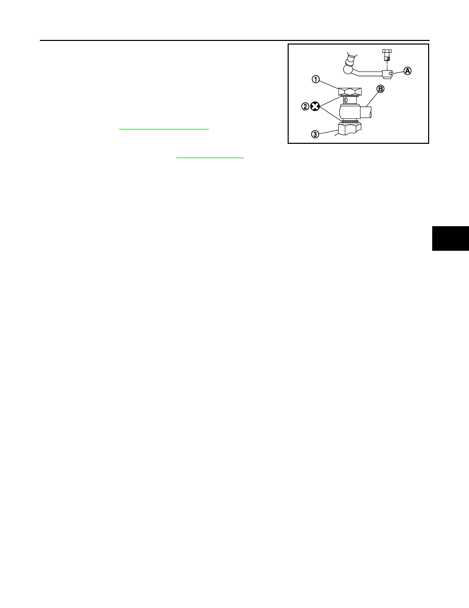
When installing eye bolt (1) and copper washers (2) to oil pump
(3), refer to the figure.

CAUTION:

• Never reuse copper washer.
• Apply power steering fluid or equivalent to around copper

washer, then install eye bolt.

• Install eye bolt with eye joint (assembled to high pressure

hose) (B) protrusion (A) facing with pump side cutout, and
then tighten it to the specified torque after tightening by
hand. Refer to 

ST-62, "Exploded View"

.

• Securely insert harness connector to pressure sensor.

7.

Check fluid level, fluid leakage and air bleeding hydraulic sys-
tem after the installation. Refer to 

ST-31, "Inspection"

.

BEFORE DISASSEMBLY

Disassemble oil pump only when the following malfunctions occur.
• If oil leakage is found on oil pump.
• Oil pump pulley is damaged or deformed.
• Performance of oil pump is low. 

AFTER DISASSEMBLY

Body Assembly and Rear Cover Inspection

• Check body assembly and rear cover for internal damage. Replace rear cover if it is damaged. Replace oil

pump assembly if body assembly is damaged.

Cartridge Assembly Inspection

• Check cam ring, rotor and vane for damage. Replace cartridge assembly if necessary.

Side Plate Inspection

• Check side plate for damage. Replace side plate if necessary.

Flow Control Valve Inspection

• Check flow control valve and spring for damage. Replace if necessary.

SGIA1379E

Revision: 2011 November

2011 MURANO

ST-62

< REMOVAL AND INSTALLATION >

[WITH HEATED STEERING WHEEL]

HYDRAULIC LINE

HYDRAULIC LINE

Exploded View

INFOID:0000000006257724

Removal and Installation

INFOID:0000000006257725

CAUTION:

1.

Reservoir tank bracket

2.

Bushing

3.

Reservoir tank

4.

Suction hose

5.

Clamp

6.

Copper washer

7.

High pressure piping

8.

Steering gear assembly

9.

Low pressure hose

10. Eye bolt

A.

To power steering oil pump suction 
hose.

B.

To power steering oil pump.

: Vehicle front

: Apply power steering fluid.

Refer to 

GI-4, "Components"

 for symbols not described on the above.

JSGIA0608GB

Revision: 2011 November

2011 MURANO

HYDRAULIC LINE

ST-63

< REMOVAL AND INSTALLATION >

[WITH HEATED STEERING WHEEL]

C

D

E

F

H

I

J

K

L

M

A

B

ST

N

O

P

• Never apply fluid to the hose (1) and tube (2).
• Insert hose securely until it contacts spool (A) of tube.
• Leave clearance (L) when installing clamp (3).

• Install eye bolt with eye joint (assembled to high pressure

hose) (B) protrusion (A) facing with pump side cutout, and
then tighten it to the specified torque after tightening by hand.
Refer to 

ST-62, "Exploded View"

.

• Securely insert harness connector to pressure sensor.
• Apply power steering fluid to around copper washer, then

install eye bolt.

• Never reuse copper washer.

Standard

L

: 3 – 8 mm (0.12 – 0.31 in)

JSGIA0118ZZ

SGIA1379E

Revision: 2011 November

2011 MURANO

ST-64

< REMOVAL AND INSTALLATION >

[WITH HEATED STEERING WHEEL]

HEATED STEERING WHEEL SWITCH

HEATED STEERING WHEEL SWITCH

Removal and Installation

INFOID:0000000006842433

REMOVAL

1.

Remove Instrument lower panel LH. Refer to 

IP-13, "Removal and Installation"

.

2.

Remove heated steering wheel switch.

INSTALLATION

Install in the reverse order of removal.

Revision: 2011 November

2011 MURANO

SERVICE DATA AND SPECIFICATIONS (SDS)

ST-65

< SERVICE DATA AND SPECIFICATIONS (SDS) 

[WITH HEATED STEERING WHEEL]

C

D

E

F

H

I

J

K

L

M

A

B

ST

N

O

P

SERVICE DATA AND SPECIFICATIONS (SDS)

SERVICE DATA AND SPECIFICATIONS (SDS)

General Specifications

INFOID:0000000006257726

Steering Wheel Axial End Play and Play

INFOID:0000000006257727

Unit: mm (in)

Steering Wheel Turning Force

INFOID:0000000006257728

Unit: N·m (kg-m, in-lb)

Steering Angle

INFOID:0000000006257729

Unit: Degree minute (Decimal degree)

Steering Column Length

INFOID:0000000006257730

Unit: mm (in)

Steering Column Mounting Dimensions

INFOID:0000000006257731

Unit: mm (in)

Steering Column Operating Range

INFOID:0000000006257732

Steering gear model

PR26AF

Fluid capacity (Approx.)

 (US qt, lmp qt)

1.0 (1-1/8, 7/8)

Item

Standard

Steering wheel axial end play

0 (0)

Steering wheel play on the outer circumference

0 – 35 (0 – 1.38)

Item

Standard

Steering wheel turning force

7.45 (0.76, 66)

Item

Standard

Wheel size: 18 inch

Wheel size: 20 inch

Inner wheel

Minimum

33

°

30

 (33.5

°

)

32

°

00

 (32.0

°

)

Nominal

36

°

30

 (36.5

°

)

35

°

00

 (35.0

°

)

Maximum

37

°

30

 (37.5

°

)

36

°′

 (36.0

°

)

Outer wheel

Nominal

31

°

30

 (31.5

°

)

30

°

30

 (30.5

°

)

Item

Standard

Column length

463 (18.23)

Item

Standard

Mounting dimension

30 (1.18) or less

Item

Standard

Without electric motor

With electric motor

Tilt operating range 

15

°

18

°

Telescopic operating range 

40 mm (1.57 in)

Rotating torque

0.49 N·m (0.05 kg-m, 4 in-lb)

Revision: 2011 November

2011 MURANO

ST-66

< SERVICE DATA AND SPECIFICATIONS (SDS) 

[WITH HEATED STEERING WHEEL]

SERVICE DATA AND SPECIFICATIONS (SDS)

Lower Shaft Length

INFOID:0000000006257733

Unit: mm (in)

Rack Sliding Force

INFOID:0000000006257734

Unit: N (kg, lb)

Rack Stroke

INFOID:0000000006257735

Unit: mm (in)

Socket Swing Force and Rotating Torque

INFOID:0000000006257736

SWING FORCE

Unit: N (kg, lb)

ROTATING TORQUE

Unit: N·m (kg-m, in-lb)

Socket Axial End Play

INFOID:0000000006257737

Unit: mm (in)

Inner Socket Length

INFOID:0000000006257738

Unit: mm (in)

Relief Oil Pressure

INFOID:0000000006257739

Unit: kPa (kg/cm

2

, psi)

Item

Standard

Lower shaft length

160 (6.3) or more

Item

Standard

2WD

AWD

Rack sliding force

195 – 258 (19.9 – 26.3, 43.8 – 

57.9)

227 – 305 (23.2 – 31.1, 51.1 – 

68.5)

Item

Standard

Wheel size: 18 inch

Wheel size: 20 inch

Rack neutral position 

70.5 (2.776)

68.0 (2.677)

Item

Standard

Outer socket

4.81 – 45.7 (0.5 – 4.6, 1.1 – 10.2)

Inner socket

8.9 – 64 (0.91 – 6.5, 2.01 – 14.3)

Item

Standard

Outer socket 

0.3 – 2.9 (0.03 – 0.29, 3 – 25)

Item

Standard

Outer socket

0.5 (0.02) or less

Inner socket

0.2 (0.008) or less

Item

Standard

Rack neutral position

120.3 (4.74)

Item

Standard

Relief oil pressure

9,500 – 10,300 (96.9 – 105.1, 1,378 – 1,494)

Revision: 2011 November

2011 MURANO

PRECAUTIONS

ST-67

< PRECAUTION >

[WITHOUT HEATED STEERING WHEEL]

C

D

E

F

H

I

J

K

L

M

A

B

ST

N

O

P

PRECAUTION

PRECAUTIONS

FOR USA AND CANADA

FOR USA AND CANADA : Precaution for Supplemental Restraint System (SRS) "AIR 
BAG" and "SEAT BELT PRE-TENSIONER"

INFOID:0000000006843204

The Supplemental Restraint System such as “AIR BAG” and “SEAT BELT PRE-TENSIONER”, used along
with a front seat belt, helps to reduce the risk or severity of injury to the driver and front passenger for certain
types of collision. This system includes seat belt switch inputs and dual stage front air bag modules. The SRS
system uses the seat belt switches to determine the front air bag deployment, and may only deploy one front
air bag, depending on the severity of a collision and whether the front occupants are belted or unbelted.
Information necessary to service the system safely is included in the “SRS AIR BAG” and “SEAT BELT” of this
Service Manual.

WARNING:

Always observe the following items for preventing accidental activation.
• To avoid rendering the SRS inoperative, which could increase the risk of personal injury or death in

the event of a collision that would result in air bag inflation, all maintenance must be performed by
an authorized NISSAN/INFINITI dealer.

• Improper maintenance, including incorrect removal and installation of the SRS, can lead to personal

injury caused by unintentional activation of the system. For removal of Spiral Cable and Air Bag
Module, see “SRS AIR BAG”.

• Never use electrical test equipment on any circuit related to the SRS unless instructed to in this Ser-

vice Manual. SRS wiring harnesses can be identified by yellow and/or orange harnesses or harness
connectors.

PRECAUTIONS WHEN USING POWER TOOLS (AIR OR ELECTRIC) AND HAMMERS

WARNING:

Always observe the following items for preventing accidental activation.
• When working near the Air Bag Diagnosis Sensor Unit or other Air Bag System sensors with the

ignition ON or engine running, never use air or electric power tools or strike near the sensor(s) with
a hammer. Heavy vibration could activate the sensor(s) and deploy the air bag(s), possibly causing
serious injury.

• When using air or electric power tools or hammers, always switch the ignition OFF, disconnect the

battery, and wait at least 3 minutes before performing any service.

FOR USA AND CANADA : Service Notice or Precautions for Steering System

INFOID:0000000006843205

• In case of removing steering gear assembly, make the final tightening with grounded and unloaded vehicle

condition, and then check wheel alignment.

• Observe the following precautions when disassembling.
- Before disassembly, thoroughly clean the outside of the unit.
- Disassembly should be done in a clean work area. It is important to prevent the internal parts from becoming

contaminated by dirt or other foreign matter.

- For easier and proper assembly, place disassembled parts in order on a parts rack.
- Use nylon cloth or paper towels to clean the parts; common shop rags can leave lint that might interfere with

their operation.

- Never reuse non-reusable parts.
- Before assembling, apply the specified grease to the directed parts.

FOR MEXICO

FOR MEXICO : Precaution for Supplemental Restraint System (SRS) "AIR BAG" and 
"SEAT BELT PRE-TENSIONER"

INFOID:0000000006843206

The Supplemental Restraint System such as “AIR BAG” and “SEAT BELT PRE-TENSIONER”, used along
with a front seat belt, helps to reduce the risk or severity of injury to the driver and front passenger for certain
types of collision. Information necessary to service the system safely is included in the “SRS AIR BAG” and
“SEAT BELT” of this Service Manual.

Revision: 2011 November

2011 MURANO

ST-68

< PRECAUTION >

[WITHOUT HEATED STEERING WHEEL]

PRECAUTIONS

WARNING:

Always observe the following items for preventing accidental activation.
• To avoid rendering the SRS inoperative, which could increase the risk of personal injury or death in

the event of a collision that would result in air bag inflation, all maintenance must be performed by
an authorized NISSAN/INFINITI dealer.

• Improper maintenance, including incorrect removal and installation of the SRS, can lead to personal

injury caused by unintentional activation of the system. For removal of Spiral Cable and Air Bag
Module, see “SRS AIR BAG”.

• Never use electrical test equipment on any circuit related to the SRS unless instructed to in this Ser-

vice Manual. SRS wiring harnesses can be identified by yellow and/or orange harnesses or harness
connectors.

PRECAUTIONS WHEN USING POWER TOOLS (AIR OR ELECTRIC) AND HAMMERS

WARNING:

Always observe the following items for preventing accidental activation.
• When working near the Air Bag Diagnosis Sensor Unit or other Air Bag System sensors with the

ignition ON or engine running, never use air or electric power tools or strike near the sensor(s) with
a hammer. Heavy vibration could activate the sensor(s) and deploy the air bag(s), possibly causing
serious injury.

• When using air or electric power tools or hammers, always switch the ignition OFF, disconnect the

battery, and wait at least 3 minutes before performing any service.

FOR MEXICO : Service Notice or Precautions for Steering System

INFOID:0000000006843207

• In case of removing steering gear assembly, make the final tightening with grounded and unloaded vehicle

condition, and then check wheel alignment.

• Observe the following precautions when disassembling.
- Before disassembly, thoroughly clean the outside of the unit.
- Disassembly should be done in a clean work area. It is important to prevent the internal parts from becoming

contaminated by dirt or other foreign matter.

- For easier and proper assembly, place disassembled parts in order on a parts rack.
- Use nylon cloth or paper towels to clean the parts; common shop rags can leave lint that might interfere with

their operation.

- Never reuse non-reusable parts.
- Before assembling, apply the specified grease to the directed parts.

Revision: 2011 November

2011 MURANO

PREPARATION

ST-69

< PREPARATION >

[WITHOUT HEATED STEERING WHEEL]

C

D

E

F

H

I

J

K

L

M

A

B

ST

N

O

P

PREPARATION

PREPARATION

Special Service Tools

INFOID:0000000006843208

The actual shapes of Kent-Moore tools may differ from those of special service tools illustrated here.

Tool number
(Kent-Moore No.)
Tool name

Description

ST27180001
(J-25726-A)
Steering wheel puller

Removing steering wheel

ST3127S000
(J-25765-A)
Preload gauge

• Measuring steering column rotating torque
• Measuring pinion rotating torque
• Measuring ball joint rotating torque

KV48104400
(

)

Teflon ring correcting tool
a: 50 mm (1.97 in) dia.
b: 36 mm (1.42 in) dia.
c: 100 mm (3.94 in)

Installing rack Teflon ring

KV48103400
(

)

Preload adapter

Measuring pinion rotating torque

ST35300000
(

)

Drift
a: 45.1 mm (1.776 in) dia.
b: 59.0 mm (2.323 in) dia.

Installing oil pump oil seal

ZZA0819D

ZZA0806D

S-NT550

ZZA0824D

ZZA0881D

Revision: 2011 November

2011 MURANO

ST-70

< PREPARATION >

[WITHOUT HEATED STEERING WHEEL]

PREPARATION

Commercial Service Tools

INFOID:0000000006843209

KV48103500
(J-26357)
Oil pressure gauge

Measuring oil pump relief pressure

KV48102500
(J-33914)
Oil pressure gauge adapter

Measuring oil pump relief pressure

Tool number
(Kent-Moore No.)
Tool name

Description

S-NT547

S-NT542

Tool name

Description

Power tool

Loosening bolts and nuts

Ball joint remover

Removing steering outer socket

Open head

Tightening end cover assembly

PBIC0190E

S-NT146

ZZA0822D

Revision: 2011 November

2011 MURANO

PREPARATION

ST-71

< PREPARATION >

[WITHOUT HEATED STEERING WHEEL]

C

D

E

F

H

I

J

K

L

M

A

B

ST

N

O

P

Drift
a: 15 mm (0.59 in) dia.
b: 10 mm (0.39 in) dia.

Installing rotor snap ring

Drift
a: 36 mm (1.42 in) dia.
b: 20 mm (0.79 in) dia.

Installing oil pump oil seal

Tool name

Description

S-NT474

S-NT474

Revision: 2011 November

2011 MURANO

ST-72

< BASIC INSPECTION >

[WITHOUT HEATED STEERING WHEEL]

STEERING WHEEL

BASIC INSPECTION

STEERING WHEEL

Inspection

INFOID:0000000006843218

NEUTRAL POSITION STEERING WHEEL

1.

Check that steering gear assembly, steering column assembly and steering wheel are installed in the cor-
rect position.

2.

Perform neutral position inspection after wheel alignment. Refer to 

FSU-8, "Inspection"

.

3.

Set the vehicle to the straight-ahead position and confirm steering wheel is in the neutral position.

4.

Loosen outer socket lock nut and turn inner socket to left and right equally to make fine adjustments if
steering wheel is not in the neutral position.

STEERING WHEEL TURNING FORCE

1.

Park the vehicle on a level and dry surface, set parking brake.

2.

Tires need to be inflated normal pressure. Refer to 

WT-52, "Tire Air Pressure"

.

3.

Start the engine.

4.

Bring power steering fluid up to adequate operating temperature.

5.

Check steering wheel turning force when steering wheel has
been turned 540

°

 from neutral position.

NOTE:
Multiply the distance (L) from the hook of spring balance to the
center of steering wheel by the measurement value with a spring
balance.

6.

If steering wheel turning force is out of the specification, check
rack sliding force and relief hydraulic pressure of oil pump. Regarding relief hydraulic pressure of oil
pump, refer to 

ST-106, "Inspection"

.

RACK SLIDING FORCE

1.

Disconnect lower joint and steering knuckle from steering gear assembly. Refer to 

ST-87, "Exploded

View"

.

2.

Start and run the engine at idle to make sure steering fluid has reached normal operating temperature.

3.

While pulling outer socket slowly in 

±

11.5 mm (

±

0.453 in) range

from neutral position, make sure rack sliding force is within
specification.

4.

If rack sliding force is not within specification, overhaul steering
gear assembly.

FRONT WHEEL TURNING ANGLE

1.

Check front wheel turning angle after toe-in inspection. Refer to 

FSU-8, "Inspection"

.

Fluid temperature

: 50 – 80

°

C (122 – 176

°

F)

Standard

Steering wheel turning 
force

: Refer to 

ST-110, "Steer-

ing Wheel Turning Force"

.

JSGIA0027ZZ

Fluid temperature

: 50 – 80

°

C (122 – 176

°

F)

Standard

Rack sliding force

: Refer to 

ST-111, "Rack 

Sliding Force"

.

SST090B

Revision: 2011 November

2011 MURANO

STEERING WHEEL

ST-73

< BASIC INSPECTION >

[WITHOUT HEATED STEERING WHEEL]

C

D

E

F

H

I

J

K

L

M

A

B

ST

N

O

P

2.

Place front wheels on turning radius gauges and rear wheels on
stands, so that vehicle can be level.

3.

Check the maximum inner and outer wheel turning angles for LH
and RH road wheels.

4.

With the engine at idle, turn steering wheel from full left stop to
full right stop and measure the turning angles.

5.

Check the following items when turning angle is out of the stan-
dard.

a.

Check the neutral position of the rack stroke (L).

b.

Disassemble steering gear assembly to check the cause that
rack stroke is outside of the standard.
• Steering angles are not adjustable. Check steering gear

assembly, steering column assembly and front suspension
components for wear or damage if any of the turning angles are different from the specified value.
Replace any of them, if any non-standard condition exists.

FAA0016D

Standard

Inner wheel (Angle: A)

: Refer to 

ST-110, "Steer-

ing Angle"

.

Outer wheel (Angle: B)

Refer to 

ST-110, "Steer-

ing Angle"

.

SGIA0055E

Standard

Rack stroke neutral position (L)

: Refer to 

ST-111, 

"Rack Stroke"

.

SGIA0629J

Revision: 2011 November

2011 MURANO

ST-74

< SYMPTOM DIAGNOSIS >

[WITHOUT HEATED STEERING WHEEL]

NOISE, VIBRATION AND HARSHNESS (NVH) TROUBLESHOOTING

SYMPTOM DIAGNOSIS

NOISE, VIBRATION AND HARSHNESS (NVH) TROUBLESHOOTING

NVH Troubleshooting Chart

INFOID:0000000006843230

2WD MODELS 

Use the chart below to find the cause of the symptom. If necessary, repair or replace these parts.

×

: Applicable

AWD MODELS (WITHOUT ELECTRIC MOTOR)

Reference

ST

-77, "

Inspe

c

tio

n

"

ST

-77, "

Inspe

c

tio

n

"

ST

-100, "

In

sp

ecti

on

"

ST

-100, "

In

sp

ecti

on

"

ST

-100, "

In

sp

ecti

on

"

ST

-77, "

Inspe

c

tio

n

"

ST

-79, "

Inspe

c

tio

n

"

ST

-79, "

Inspe

c

tio

n

"

EM-17, "

Ch

ec

ki

ng

"

ST

-79, "

Inspe

c

tio

n

"

ST

-90, "

Ex

pl

od

ed

 V

iew

"


ST

-82, "

WITHOUT 

ELECTRI

C

 MOT

O

R : I

n

spe

c

ti

on

"


ST

-81, "

WITHOUT 

ELECTRI

C

 MOT

O

R : Ex

pl

od

ed

 V

iew

"

ST

-90, "

Ex

pl

od

ed

 V

iew

"

NV

in

 F

A

X

, R

A

X

FS

U

, R

S

se

ct

ion

.

NV

H in

 WT se

cti

on

.

NV

H in

 WT se

cti

on

.

NV

in

 F

A

X

 se

ct

ion

.

NV

in

 B

R

 s

ec

tio

n.

Possible cause and SUSPECTED PARTS

F

lui

d l

ev

el

Ai

r i

n

 hy

dra

u

lic sy

st

em

Ou

ter/

inn

e

so

ck

et

 ba

ll 

joi

n

t swi

n

g

ing

 to

rqu

e

Ou

ter/

inn

e

so

ck

et

 ba

ll 

joi

n

t rot

a

ti

ng

 tor

que

Ou

ter/

inn

e

so

ck

et

 ba

ll 

joi

n

t en

d p

la

y

S

te

eri

ng

 fl

ui

d

 l

e

ak

ag

e

S

te

e

ri

ng

 whe

e

l pl

ay

S

te

e

ri

ng

 ge

ar rac

k sl

id

in

g

 fo

rce

Dri

v

e

 be

lt 

lo

os

en

es

s

Im

pro

p

e

r st

ee

ri

ng

 wh

ee

l

Im

p

rop

er i

n

s

tal

la

tio

n

 o

r lo

os

en

es

s

 of

 til

t l

o

c

k

 l

e

v

e

r

M

ou

nt

ing

 lo

os

e

nes

s

S

tee

rin

g

 c

o

lum

n

 de

form

at

ion

 o

r da

ma

ge

Im

p

rop

er i

n

s

tal

la

tio

n

 o

r lo

os

en

es

s

 of

 st

ee

ring

 c

o

lu

m

n

S

te

e

ri

ng

 li

nk

ag

e l

o

o

se

n

e

ss

A

XLE and 

SUSP

ENSION

TI

RE

ROAD W

H

EEL

DRIV

E SHAFT

BR

AK

E

Symptom

Steering

Noise

×

×

×

×

×

×

×

×

×

×

×

×

×

×

×

×

Shake

×

×

×

×

×

×

×

×

Vibration

×

×

×

×

×

×

×

×

Shimmy

×

×

×

×

×

×

×

Judder

×

×

×

×

×

×

×

Revision: 2011 November

2011 MURANO

NOISE, VIBRATION AND HARSHNESS (NVH) TROUBLESHOOTING

ST-75

< SYMPTOM DIAGNOSIS >

[WITHOUT HEATED STEERING WHEEL]

C

D

E

F

H

I

J

K

L

M

A

B

ST

N

O

P

Use the chart below to find the cause of the symptom. If necessary, repair or replace these parts.

×

: Applicable

AWD MODELS (WITH ELECTRIC MOTOR)

Reference

ST

-77,

 "

In

sp

ectio

n

"

ST

-77,

 "

In

sp

ectio

n

"

ST

-100, "

In

sp

ec

tio

n

"

ST

-100, "

In

sp

ec

tio

n

"

ST

-100, "

In

sp

ec

tio

n

"

ST

-77,

 "

In

sp

ectio

n

"

ST

-79,

 "

In

sp

ectio

n

"

ST

-79,

 "

In

sp

ectio

n

"

EM-17,

 "

Ch

ec

ki

ng

"

ST

-79,

 "

In

sp

ectio

n

"

ST

-90,

 "

Exp

lod

ed

 V

iew

"

ST

-82,

 "

WIT

H

OUT 

ELECT

R

IC M

O

T

O

R : I

n

spe

c

ti

on

"


ST

-81,

 "

WIT

H

OUT 

ELECT

R

IC M

O

T

O

R : E

x

p

lod

ed

 V

ie

w

"

ST

-90,

 "

Exp

lod

ed

 V

iew

"

NVH in DLN section.

NVH in DLN section.

NVH in F

A

X, RAX, 

FSU, RSU 

section.

NVH in WT 

section.

NVH in WT 

section.

NVH in F

A

X, RAX 

section.

NVH in BR section.

Possible cause and SUSPECTED PARTS

Flu

id leve

l

Ai

r in

 hy

dra

u

lic

 sy

st

em

Ou

te

r/in

ne

r so

ck

et

 ba

ll jo

int

 s

w

in

g

in

g

 t

o

rqu

e

Ou

te

r/in

ne

r so

cket

 ba

ll jo

int

 rot

a

ti

ng

 to

rqu

e

Ou

te

r/in

ne

r so

ck

et

 ba

ll jo

int

 en

pla

y

S

tee

ri

ng

 f

lui

le

a

ka

g

e

S

tee

ri

ng

 wh

ee

l p

lay

S

te

e

rin

g

 ge

ar ra

ck

 s

lid

in

g f

o

rc

e

Dri

v

e

 b

elt

 lo

os

en

es

s

Imp

rop

er ste

e

ri

ng

 whe

e

l

Im

pro

pe

in

st

al

lat

ion

 o

r lo

os

en

es

s o

f t

ilt

 lo

ck

 l

e

ve

r

M

ou

nt

ing

 lo

os

en

es

s

S

tee

ri

ng

 c

o

lu

m

n

 d

e

fo

rmat

io

n

 or da

ma

ge

Im

pro

pe

in

st

al

lat

ion

 o

r lo

os

en

es

s o

f st

e

eri

ng

 co

lu

mn

S

te

erin

g lin

ka

ge

 lo

os

en

es

s

PROP

ELLER SHAFT

D

IFFERENTIAL

AXLE and 

S

U

S

PENSION

TIRE

R

O

AD WHEEL

D

R

IVE SHAF

T

BRAKE

Symptom

Steering

Noise

× × × × × × × × ×

× ×

× × × × × × ×

Shake

× × ×

×

× × × × ×

Vibration

× × × × ×

×

× ×

×

Shimmy

×

×

×

× × ×

×

Judder

× ×

×

× × ×

×

Revision: 2011 November

2011 MURANO

ST-76

< SYMPTOM DIAGNOSIS >

[WITHOUT HEATED STEERING WHEEL]

NOISE, VIBRATION AND HARSHNESS (NVH) TROUBLESHOOTING

Use the chart below to find the cause of the symptom. If necessary, repair or replace these parts.

×

: Applicable

Reference

ST

-7

7,

 "

Inspe

c

ti

on

"

ST

-7

7,

 "

Inspe

c

ti

on

"

ST

-1

00

, "

In

sp

ectio

n

"

ST

-1

00

, "

In

sp

ectio

n

"

ST

-1

00

, "

In

sp

ectio

n

"

ST

-7

7,

 "

Inspe

c

ti

on

"

ST

-7

9,

 "

Inspe

c

ti

on

"

ST

-7

9,

 "

Inspe

c

ti

on

"

EM

-1

7

, "

Checking

"

ST

-7

9,

 "

Inspe

c

ti

on

"

ST

-9

0,

 "

Ex

pl

od

ed

 V

iew

"

ST

-8

5,

 "

WITH 

E

L

ECTRIC MOT

O

R : 

In

sp

ecti

on

"

ST

-8

4,

 "

WITH E

L

ECTRIC 

MOT

O

: Ex

pl

od

ed

 V

iew

"


ST

-9

0,

 "

Ex

pl

od

ed

 V

iew

"

NVH in DLN 

section.

NVH in DLN 

section.

NVH in F

AX, 

RAX, FSU, 

RSU section.

NVH in WT 

section.

NVH in WT 

section.

NVH in F

AX,

 RAX 

secti

on.

NVH in BR 

section.

Possible cause and SUSPECTED PARTS

Fl

ui

d l

e

v

e

l

Ai

r in

 hy

d

raul

ic

 s

y

s

tem

Ou

ter/i

n

n

e

s

o

ck

et ba

ll joi

n

t swin

gi

ng

 to

rqu

e

Ou

ter/i

n

n

e

so

cket ba

ll joi

n

t rot

a

tin

g

 torq

ue

Ou

ter/i

n

n

e

s

o

ck

et ba

ll joi

n

t en

p

la

y

S

tee

rin

g

 f

lui

d l

e

a

k

a

g

e

S

te

e

ri

ng

 whe

e

l pl

ay

S

te

e

ri

ng

 ge

ar ra

ck s

lid

in

g f

o

rc

e

Dri

ve b

el

lo

os

en

es

s

Im

p

rope

r s

tee

rin

g

 wh

ee

l

Im

p

rope

r i

n

s

tal

lat

io

n

 o

r lo

os

en

es

of 

til

t lo

ck

 l

e

v

e

r

M

ou

nti

ng

 lo

os

en

es

s

S

tee

rin

g

 c

o

lu

m

n

 d

e

fo

rm

ati

o

n

 or 

da

ma

ge

Im

p

rope

r i

n

s

tal

lat

io

n

 o

r lo

os

en

es

of 

ste

e

ri

ng

 c

o

lu

mn

S

tee

rin

g l

ink

a

ge 

lo

os

en

es

s

PROPELLER SHAFT

DIF

F

ERENTIA

L

AX

LE and SUSPE

N

S

ION

TI

RE

ROAD WHE

E

L

DRIVE

 SHAFT

BRAK

E

Symptom

Steering

Noise

× × × × × × × × ×

× ×

× × × × × × ×

Shake

× × ×

×

× × × × ×

Vibration

× × × × ×

×

× ×

×

Shimmy

×

×

×

× × ×

×

Judder

× ×

×

× × ×

×

Revision: 2011 November

2011 MURANO


Content      ..     53      54      55      56     ..