Nissan Murano Z50 (2007 year). Manual - part 82
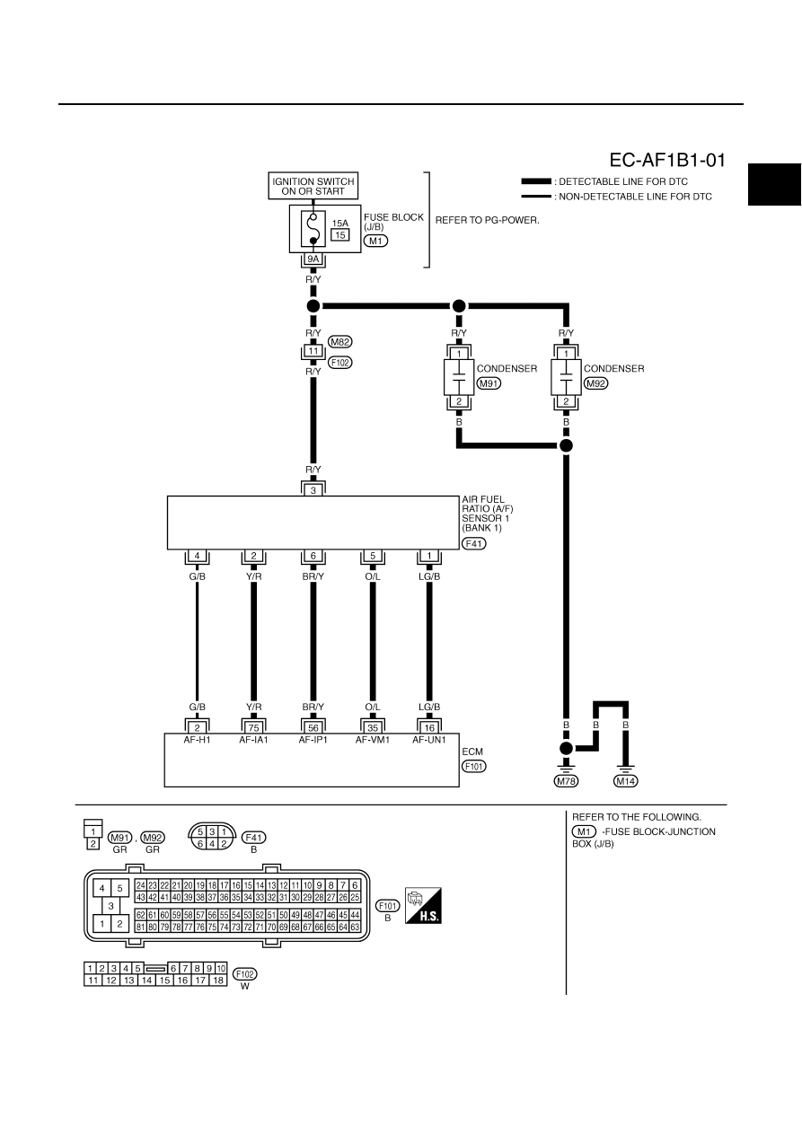
DTC P0133, P0153 A/F SENSOR 1
EC-261
C
D
E
F
G
H
I
J
K
L
M
A
EC
Revision: 2006 July
2007 Murano
Wiring Diagram
NBS003AG
BANK 1
TBWM1631E
|
|
|
DTC P0133, P0153 A/F SENSOR 1 EC-261 C D E F G H I J K L M A EC Revision: 2006 July 2007 Murano Wiring Diagram NBS003AG BANK 1 TBWM1631E |