Nissan Murano Z50 (2007 year). Manual - part 24
INTELLIGENT KEY SYSTEM
BL-129
C
D
E
F
G
H
J
K
L
M
A
B
BL
Revision: 2006 July
2007 Murano
DOOR LOCK/UNLOCK FUNCTION MALFUNCTION
NOTE:
●
Before performing the diagnosis in the following table, check “Trouble Diagnosis Procedure”. Refer to
121, "Trouble Diagnosis Procedure"
●
Make sure that vehicle is under the condition shown in “Conditions of vehicle” before starting diagnosis,
and check each symptom.
●
If the following “symptoms” are detected, check systems shown in the “Diagnosis/Service procedure” col-
umn in this order.
Conditions of Vehicle (Operating Conditions)
●
LOCK/UNLOCK BY I-KEY is ON when setting on CONSULT-II.
●
Ignition switch is not depressed.
●
All doors are closed.
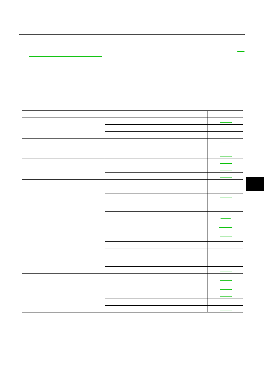
Symptom
Diagnosis/Service procedure
Reference page
Door lock/unlock do not operate by request
switch.
1.
Check door switch.
2.
Check ignition knob switch.
3.
Replace Intelligent Key unit.
Door lock/unlock does not operate by request
switch (driver side).
1.
Check door request switch (driver side).
2.
Check outside key antenna (driver side).
3.
Replace Intelligent Key unit.
Door lock/unlock does not operate by request
switch (passenger side).
1.
Check door request switch (passenger side).
2.
Check outside key antenna (passenger side).
3.
Replace Intelligent Key unit.
Door lock/unlock does not operate by request
switch (back door).
1.
Check door request switch (back door).
2.
Check outside key antenna (rear bumper).
3.
Replace intelligent key unit.
Selective unlock function does not operate by
request switch (driver side). (Other door lock
function operate properly)
1.
Check “SELECTIVE UNLOCK FUNCTION” setting in
“WORK SUPPORT”.
2.
Check select unlock function with a remote controller
or door key cylinder.
3.
Replace BCM.
Selective unlock function does not operate by
request switch (passenger side). (Other door
lock function operate properly)
1.
Check “SELECTIVE UNLOCK FUNCTION” setting in
“WORK SUPPORT”.
2.
Check select unlock relay.
3.
Replace Intelligent Key unit.
Selective unlock function dose not operate by
request switch (back door).
1.
Check “SELECTIVE UNLOCK FUNCTION” setting in
“WORK SUPPORT”.
2.
Replace Intelligent Key unit.
Auto lock function does not operate properly.
1.
Check “AUTO RELOCK TIMER” setting in “WORK
SUPPORT”.
2.
Check key switch.
3.
Check ignition knob switch.
4.
Check door switch.
5.
Replace Intelligent Key unit.