Nissan Murano Z50 (2006 year). Manual - part 169
INTERIOR ROOM LAMP
LT-203
C
D
E
F
G
H
I
J
L
M
A
B
LT
Revision: 2006 August
2006 Murano
Terminals and Reference Values for BCM
NKS001RE
*1: With Intelligent Key
*2: Without Intelligent Key
How to Proceed with Trouble Diagnosis
NKS001RF
1.
Confirm the symptom or customer complaint.
2.
Understand operation description and function description. Refer to
.
3.
Carry out the Preliminary Check. Refer to
4.
Check symptom and repair or replace the cause of malfunction.
5.
Does the interior room lamp operate normally? If YES, GO TO 6. If NO, GO TO 4.
Terminal
No.
Wire color
Signal name
Measuring condition
Reference value
Ignition
switch
Operation or condition
1
R/Y
Ignition key hole illumination
signal
OFF
Door is locked. (SW OFF)
Battery voltage
Door is unlocked. (SW ON)
Approx. 0 V
12
R/G
*1
R
*2
Front door switch AS signal
OFF
Front door
switch AS
ON (open)
Approx. 0 V
OFF (closed)
Battery voltage
13
R/W
*1
R/Y
*2
Rear door switch RH signal
OFF
Rear door
switch RH
ON (open)
Approx. 0 V
OFF (closed)
Battery voltage
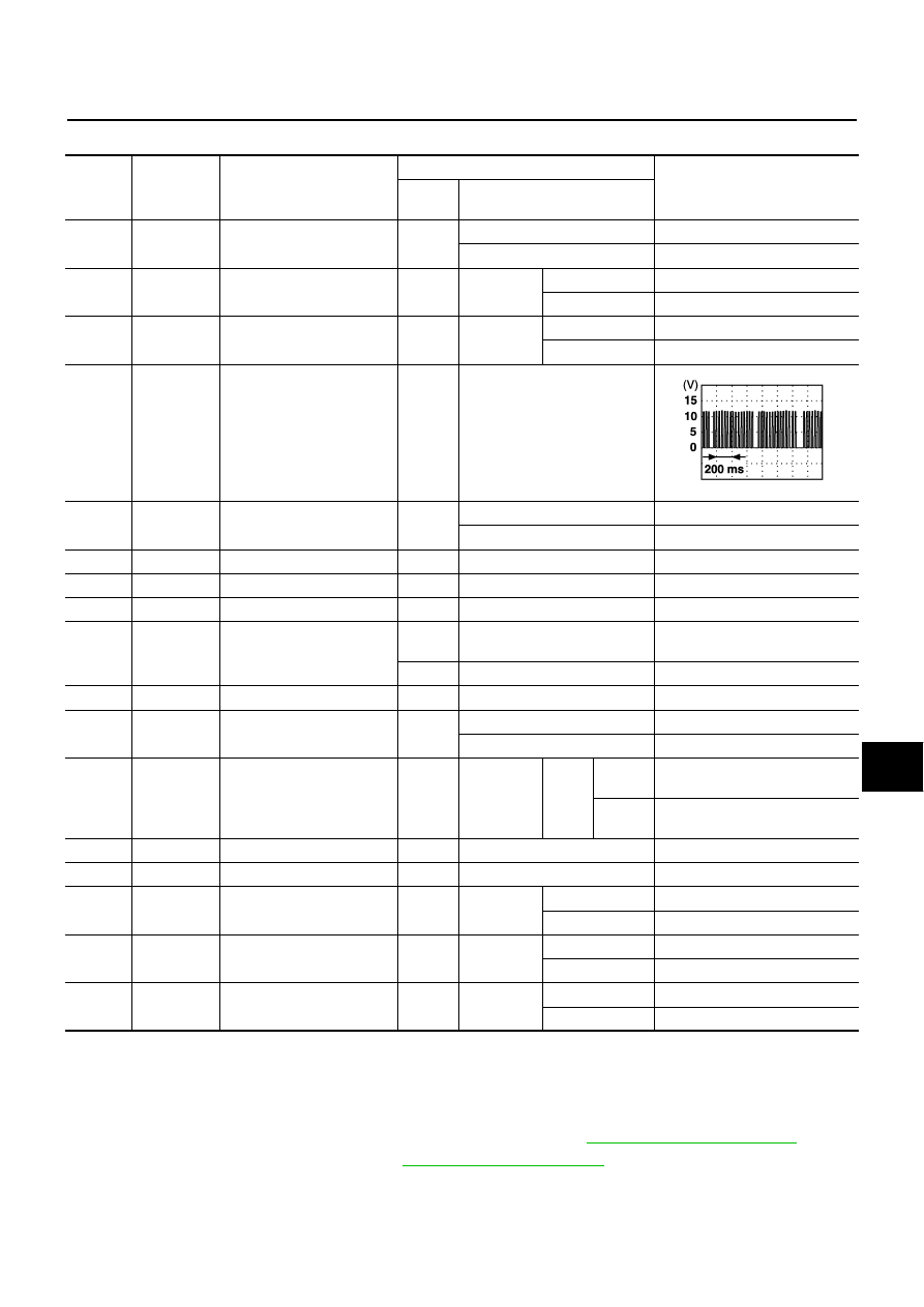
22
BR/W
Power window switch serial
link
—
—
37
B/R
Key-in detection switch
signal
OFF
Vehicle key is removed.
Approx. 0 V
Vehicle key is inserted.
Battery voltage
38
R
Ignition power supply
ON
—
Battery voltage
39
L
CAN
−
H
—
—
—
40
Y
CAN
−
L
—
—
—
41
P
Battery saver output signal
OFF
30 minutes after ignition switch
is turned to OFF.
Approx. 0 V
ON
—
Battery voltage
42
GR
Battery power supply
OFF
—
Battery voltage
47
R/W
Step lamp signal
OFF
Any door is open. (ON)
Approx. 0 V
All doors are closed. (OFF)
Battery voltage
48
R
Personal lamp LH and RH,
and room lamp illumination
output signal
OFF
Interior
door switch:
DOOR
position
Any
door
switch
ON
(open)
Approx. 0 V
OFF
(closed)
Battery voltage
52
B
Ground
ON
—
Approx. 0 V
55
W/B
Battery power supply
OFF
—
Battery voltage
58
V/W
Back door switch signal
OFF
Back door
switch
ON (open)
Approx. 0 V
OFF (closed)
Battery voltage
62
SB
Front door switch DR signal
OFF
Front door
switch DR
ON (open)
Approx. 0 V
OFF (closed)
Battery voltage
63
R/W
Rear door switch LH signal
OFF
Rear door
switch LH
ON (open)
Approx. 0 V
OFF (closed)
Battery voltage
PIIA2344J