Nissan Murano Z50 (2006 year). Manual - part 143


  Index      Manuals     Nissan Murano Z50 (2006 year) - Service and Repair Manual


Search            copyright infringement  


Content      ..     141      142      143      144     ..


Nissan Murano Z50 (2006 year). Manual - part 143


GW-88

REAR WINDOW DEFOGGER

Revision: 2006 August

2006 Murano

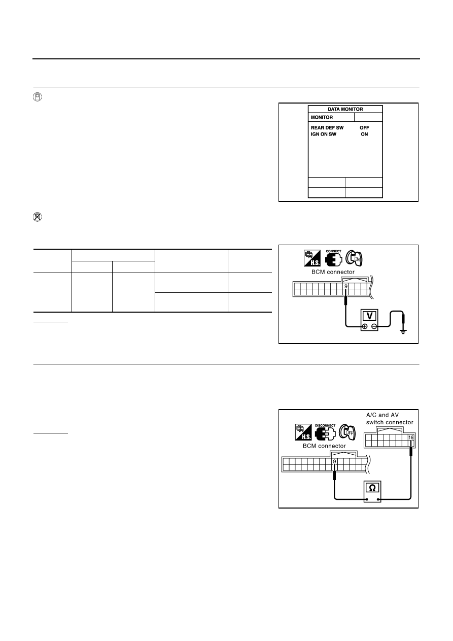
Check Rear Window Defogger Switch Circuit

NIS001C9

1. 

CHECK REAR WINDOW DEFOGGER SWITCH OPERATION 

 With CONSULT-II

Check (“REAR DEF SW”, “IGN ON SW”) in DATA MONITOR mode
with CONSULT-II.

 With out CONSULT-II

1.

Turn ignition switch ON.

2.

Check voltage between BCM connector ground.

OK or NG

OK

>> Rear window defogger switch check is OK.

NG

>> GO TO 2.

2. 

CHECK HARNESS CONTINUITY

1.

Turn ignition switch OFF.

2.

Disconnect BCM and A/C and AV switch connector.

3.

Check continuity between BCM connector M34 terminal 9 and A/C and AV switch connector M48 terminal
16.

OK or NG

OK

>> GO TO 3.

NG

>> Repair or replace harness.

When rear window defogger switch is turned to ON

REAR DEF SW

: ON

When ignition switch is turned to ON

IGN ON SW

: ON

PIIA2373E

Connector

Terminal (Wire color)

Condition

Voltage (V)

(Approx.)

(+)

(–)

M34

9 (G/W)

Ground

Rear window defogger 
switch is pressed.

0

Rear window defogger 
switch is OFF.

5

PIIA6208E

9 (G/W) – 16(G/W) 

: Continuity should exist.

PIIA9681E

REAR WINDOW DEFOGGER

GW-89

C

D

E

F

G

H

J

K

L

M

A

B

GW

Revision: 2006 August

2006 Murano

3. 

CHECK BCM OUTPUT SIGNAL

1.

Connect BCM connector.

2.

Turn ignition switch ON.

3.

Check voltage between BCM connector M34 terminal 9 and
ground.

OK or NG

OK

>> Replace A/C and AV switch.

NG

>> Replace BCM.

Check Rear Window Defogger Power Supply Circuit

NIS001CA

1. 

CHECK FUSE 

Check 10A fuse [No.12, located in the fuse block (J/B)]

Check 20A fuse (No.75, located in the IPDM E/R)

Check 20A fuse (No.80, located in the IPDM E/R)

NOTE:
Refer to 

GW-75, "Component Parts and Harness Connector Location"

 .

OK or NG

OK

>> GO TO 2.

NG

>> If fuse is blown, be sure to eliminate cause of malfunction before installing new fuse, refer to 

PG-

3, "POWER SUPPLY ROUTING CIRCUIT"

 .

2. 

CHECK POWER SUPPLY CIRCUIT

1.

Turn ignition switch OFF.

2.

Disconnect rear window defogger relay.

3.

Turn ignition switch ON.

4.

Check voltage between rear window defogger relay connector
B8 terminals 1, 3, 6 and ground.

OK or NG

OK

>> GO TO 3.

NG

>> Repair or replace harness.

9 (G/W) – Ground

: Approx. 5

PIIA6208E

1 (G) – Ground

: Battery voltage

3 (L) – Ground

: Battery voltage

6 (W) – Ground

: Battery voltage

PIIA4233E

GW-90

REAR WINDOW DEFOGGER

Revision: 2006 August

2006 Murano

3. 

CHECK REAR WINDOW DEFOGGER RELAY

Check continuity between rear window defogger terminals 3 and 5, 6 and 7.

OK or NG

OK

>> GO TO 4.

NG

>> Replace rear window defogger relay.

4. 

CHECK GROUND CIRCUIT

1.

Installation rear window defogger relay.

2.

Turn ignition switch ON.

3.

Check voltage between IPDM E/R connector and ground.

OK or NG

OK

>> Rear window defogger power supply circuit check is OK.

NG

>> GO TO 5.

5. 

CHECK HARNESS CONTINUITY

1.

Turn ignition switch OFF.

2.

Disconnect IPDM E/R connector and rear window defogger relay.

3.

Check continuity between IPDM E/R connector E9 terminal 52 and rear window defogger relay connector
B8 terminal 2.

OK or NG

OK

>> Check the condition of the harness and the connector.

NG

>> Repair or replace harness.

Terminal

Condition

Continuity

3

5

12V direct current supply 
between terminals 1 and 2

Yes

No current supply

No

6

7

12V direct current supply 
between terminals 1 and 2

Yes

No current supply

No

SEC202B

Connector

Terminals (Wire color)

Condition

Voltage (V)

(Approx.)

(+)

(-)

E9

52 (G/R)

Ground

When rear window defog-
ger switch ON

0

When rear window defog-
ger switch OFF

Battery 
voltage

PIIA6210E

52 (G/R) – 2 (G/R)

: Continuity should exist.

PIIA6211E

REAR WINDOW DEFOGGER

GW-91

C

D

E

F

G

H

J

K

L

M

A

B

GW

Revision: 2006 August

2006 Murano

Rear Window Defogger Circuit Check

NIS001CB

1. 

CHECK POWER SUPPLY CIRCUIT 

1.

Turn ignition switch OFF.

2.

Disconnect rear window defogger connector.

3.

Turn ignition switch ON.

4.

Check voltage between rear window defogger connector  and ground.

OK or NG

OK

>> GO TO 2.

NG

>> GO TO 3.

2. 

CHECK GROUND CIRCUIT

1.

Turn ignition switch OFF.

2.

Check continuity between rear window defogger connector D107 terminal 2 and ground.

OK or NG

OK

>> Check filament.  Refer to 

GW-96, "Check Filament"

If filament is OK.
Check the condition of the harness and the connector.

If filament is NG.
Repair filament.

NG

>> Repair or replace harness.

3. 

CHECK HARNESS CONTINUITY

1.

Turn ignition switch OFF.

2.

Disconnect rear window defogger relay.

3.

Check continuity between rear window defogger relay connector B8 terminal 5 and rear window defogger
connector D97 terminal 1.

OK or NG

OK

>> Check the condition of the harness and the connector.

NG

>> Repair or replace harness rear window defogger relay

and rear window defogger. When there is malfunction
inside back door, replace the back door.

Connector

Terminal (Wire color)

Condition

Voltage (V)

(Approx.)

(+)

(–)

D97

1 (G)

Ground

Rear window defogger 
switch ON.

 Battery voltage

Rear window defogger  
switch OFF.

0

PIIA4234E

2 (B) 

 Ground

: Continuity should exist.

PIIA4235E

5 (G) – 1 (G)

: Continuity should exist.

PIIA4236E

GW-92

REAR WINDOW DEFOGGER

Revision: 2006 August

2006 Murano

Check Door Mirror Defogger Power Supply Circuit 

NIS001CC

1. 

CHECK FUSE 

Check 10A fuse [No. 8, located in the fuse block (J/B)]
NOTE:
Refer to 

GW-75, "Component Parts and Harness Connector Location"

 .

OK or NG

OK

>> GO TO 2.

NG

>> If fuse is blown, be sure to eliminate cause of malfunction before installing new fuse.  Refer to 

PG-

3, "POWER SUPPLY ROUTING CIRCUIT"

 .

2. 

CHECK POWER SUPPLY CIRCUIT 1

1.

Turn ignition switch ON.

2.

Check voltage between fuse block (J/B) connector and ground.

OK or NG

OK

>> GO TO 3.

NG

>> Repair or replace harness.

3. 

CHECK POWER SUPPLY CIRCUIT 2

Check voltage between fuse block (J/B) connector and ground.

OK or NG

OK

>> GO TO 4. 

NG

>> Replace fuse block (J/B).

Connector

Terminal (Wire color)

Condition

Voltage (V)

(Approx.)

(+)

(–)

E101

2C (G)

Ground

Rear window defogger 
switch ON

 Battery voltage

Rear window defogger 
switch OFF

0

PIIA2388E

Connector

Terminal (Wire color)

Condition

Voltage (V)

(Approx.)

(+)

(–)

M2

5B (L/B)

Ground

Rear window defogger 
switch ON

 Battery voltage

Rear window defogger 
switch OFF

0

PIIA2386E

REAR WINDOW DEFOGGER

GW-93

C

D

E

F

G

H

J

K

L

M

A

B

GW

Revision: 2006 August

2006 Murano

4. 

CHECK HARNESS CONTINUITY 

1.

Turn ignition switch OFF.

2.

Disconnect fuse block (J/B) and door mirror connector.

3.

Check continuity between fuse block (J/B) connector M2 terminal 5B and door mirror connector D2 (driver
side) or D32 (passenger side) terminal 6.

OK or NG

OK

>> Check the condition of the harness and the connector.

NG

>> Repair or replace harness.

Check Driver Side Door Mirror Defogger Circuit

NIS001CD

1. 

CHECK POWER SUPPLY CIRCUIT 

1.

Turn ignition switch OFF.

2.

Disconnect door mirror (driver side) connector. 

3.

Turn ignition switch ON.

4.

Check voltage between door mirror (driver side) connector and ground.

OK or NG

OK

>> GO TO 2.

NG

>> Repair or replace harness.

2. 

CHECK GROUND CIRCUIT

1.

Turn ignition switch OFF.

2.

Check continuity between door mirror (driver side) connector D2
terminal 5 and ground.

OK or NG

OK

>> GO TO 3.

NG

>> Repair or replace harness.

5B (L/B) – 6 (L/B)

: Continuity should exist.

PIIB4188E

Connector

Terminal (Wire color)

Condition

Voltage (V)

(Approx.)

(+)

(–)

D2

6 (L/B)

Ground

Rear window defogger 
switch ON

 Battery voltage

Rear window defogger  
switch OFF

0

PIIB4190E

5 (B) – Ground

: Continuity should exist.

PIIB4189E

GW-94

REAR WINDOW DEFOGGER

Revision: 2006 August

2006 Murano

3. 

CHECK DOOR MIRROR DEFOGGER 

Check continuity between door mirror terminals 6 and 5.

OK or NG

OK

>> Check the condition of the harness and the connector.

NG

>> Replace door mirror (driver side).

Check Passenger Side Door Mirror Defogger Circuit

NIS001CE

1. 

CHECK POWER SUPPLY CIRCUIT

1.

Turn ignition switch OFF.

2.

Disconnect door mirror (passenger side) connector.

3.

Turn ignition switch ON.

4.

Check voltage between door mirror (passenger side) connector and ground.

OK or NG

OK

>> GO TO 2.

NG

>> Repair or replace harness.

2. 

CHECK GROUND CIRCUIT

1.

Turn ignition switch OFF.

2.

Check continuity between door mirror (passenger side) connector D32 terminal 5 and ground.

OK or NG

OK

>> GO TO 3.

NG

>> Repair or replace harness.

6  –  5

: Continuity should exist.

PIIB4191E

Connector

Terminal (Wire color)

Condition

Voltage (V)

(Approx.)

(+)

(–)

D32

6 (L/B)

Ground

Rear window defogger 
switch ON

 Battery voltage

Rear window defogger 
switch OFF

0

PIIB4190E

5 (B) – Ground

: Continuity should exist.

PIIB4189E

REAR WINDOW DEFOGGER

GW-95

C

D

E

F

G

H

J

K

L

M

A

B

GW

Revision: 2006 August

2006 Murano

3. 

CHECK DOOR MIRROR DEFOGGER 

Check continuity between door mirror terminals 6 and 5.

OK or NG

OK

>> Check the condition of the harness and the connector.

NG

>> Replace door mirror (passenger side).

Check Rear Window Defogger Signal

NIS001CF

1. 

CHECK REAR WINDOW DEFOGGER SWITCH LAMP

A/C and AV switch self-diagnosis is executed. Refer to 

AV-101, "A/C and AV Switch Self-Diagnosis Function"

OK or NG

OK

>> GO TO 2.

NG

>> Replace A/C and AV switch.

2. 

CHECK AV COMMUNICATION LINE

AV communication line check is executed.  Refer to.

AV-107, "Unable to Operate System with A/C and AV

Switch"

 .

OK or NG

OK

>> GO TO 3.

NG

>> Replace display control unit.

3. 

CHECK CAN COMMUNICATION LINE

CAN communication check is executed. Refer to 

AV-106, "CAN Communication Check"

 .

OK or NG

OK

>> Check the condition of the harness and the connector.

NG

>> In addition, it is necessary to check CAN communication line. Refer to 

AV-106, "CAN Communica-

tion Check"

 .

6  –  5

: Continuity should exist.

PIIB4191E

Does rear window defogger switch light?

Is rear window defogger displayed on the display?

GW-96

REAR WINDOW DEFOGGER

Revision: 2006 August

2006 Murano

Check Filament

NIS001CG

1.

When measuring voltage, wrap tin foil around the top of the neg-
ative probe. Then press the foil against the wire with your finger.

2.

Attach probe circuit tester (in Volt range) to middle portion of
each filament.

3.

If a filament is burned out, circuit tester registers 0 or battery
voltage.

4.

To locate burned out point, move probe to left and right along fil-
ament. Test needle will swing abruptly when probe passes the
point.

Filament Repair

NIS001CH

REPAIR EQUIPMENT

Conductive silver composition (Dupont No. 4817 or equivalent)

Ruler 30 cm (11.8 in) long

Drawing pen

Heat gun

Alcohol

Cloth

SEL122R

SEL263

SEL265

REAR WINDOW DEFOGGER

GW-97

C

D

E

F

G

H

J

K

L

M

A

B

GW

Revision: 2006 August

2006 Murano

REPAIRING PROCEDURE

1.

Wipe broken heat wire and its surrounding area clean with a
cloth dampened in alcohol.

2.

Apply a small amount of conductive silver composition to tip of
drawing pen.
Shake silver composition container before use.

3.

Place ruler on glass along broken line. Deposit conductive silver
composition on break with drawing pen. Slightly overlap existing
heat wire on both sides [preferably 5 mm (0.20 in)] of the break.

4.

After repair has been completed, check repaired wire for conti-
nuity. This check should be conducted 10 minutes after silver
composition is deposited.
Do not touch repaired area while test is being conducted.

5.

Apply a constant stream of hot air directly to the repaired area
for approximately 20 minutes with a heat gun. A minimum dis-
tance of 3 cm (1.2 in) should be kept between repaired area and
hot air outlet.
If a heat gun is not available, let the repaired area dry for 24
hours.

PIIA0215E

SEL012D

SEL013D

GW-98

DOOR MIRROR

Revision: 2006 August

2006 Murano

DOOR MIRROR

PFP:96301

Automatic Drive Positioner Interlocking Door Mirror 

NIS001CI

Automatic drive positioner interlocking door mirror. Refer to 

SE-12, "AUTOMATIC DRIVE POSITIONER"

 .

DOOR MIRROR

GW-99

C

D

E

F

G

H

J

K

L

M

A

B

GW

Revision: 2006 August

2006 Murano

Power Door Mirror (Only Manual Operation Model)

NIS001CJ

WIRING DIAGRAM –MIRROR–

TIWB0806E

GW-100

DOOR MIRROR

Revision: 2006 August

2006 Murano

Removal and Installation

NIS001CK

CAUTION:

Be careful not to damage the mirror bodies.

REMOVAL

1.

Remove the front door finisher. Refer to 

EI-30, "DOOR FINISHER"

 .

2.

Remove the front door sash cover.

3.

Remove the door mirror harness connector.

4.

Remove the door mirror mounting nuts, and remove the door mirror assembly.

INSTALLATION

Install in the reverse order of removal.

Disassembly and Assembly

NIS001CL

DISASSEMBLY

1.

Place the mirror body with mirror glass facing upward.

2.

Put a strip of protective tape on mirror body.

3.

As shown in the figure insert a small slotted screwdriver into the
recess between mirror base (mirror holder) and mirror holder
bracket and push up two pawls to remove mirror holder lower
half side. 

NOTE:
When pushing up pawls do not attempt to use one recess only,
be sure to push up with both recesses.
Insert screwdriver into recesses, and push up while rotating
(twist) to make work easier.

4.

Remove two terminals of mirror heater attachment.

5.

Lightly lift up lower side of mirror surface from mirror surface, and detach two pawls of upper side as if
pulling it out. Remove mirror surface from mirror body.

1.

Door mirror assembly

2.

Front door sash cover

PIIA4001E

PIIA4002E

DOOR MIRROR

GW-101

C

D

E

F

G

H

J

K

L

M

A

B

GW

Revision: 2006 August

2006 Murano

NOTE:
Be certain not to allow grease on sealing agent in center of mirror body assembly (actuator) or back side
of mirror surface (mirror holder).

ASSEMBLY

1.

Place mirror holder bracket and mirror body assembly (actuator) in a horizontal position.

2.

Connect two terminals of heater installed mirror.

3.

Fit the upper two pawls on the mirror face onto the mirror holder
bracket first, then press the lower side of mirror face until a click
sound is heard to engage the lower pawls.

NOTE:
After installation, visually make sure lower two pawls are
securely engaged from the bottom of mirror face.

PIIA4003E

GW-102

DOOR MIRROR

Revision: 2006 August

2006 Murano

IDX-1

A

C

D

E

F

G

H

I

J

K

L

B

IDX

ALPHABETICAL INDEX

M  INDEX

SECTION 


Content      ..     141      142      143      144     ..