Nissan Murano Z50 (2005 year). Manual - part 228
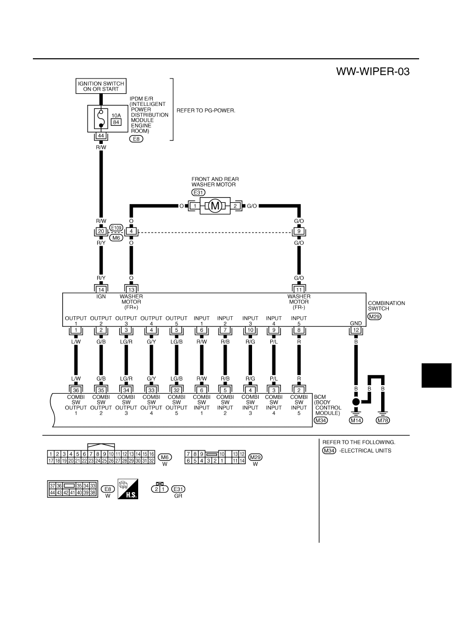
FRONT WIPER AND WASHER SYSTEM
WW-13
C
D
E
F
G
H
I
J
L
M
A
B
WW
Revision: 2005 August
2005 Murano
TKWB0903E
|
|
|
FRONT WIPER AND WASHER SYSTEM WW-13 C D E F G H I J L M A B WW Revision: 2005 August 2005 Murano TKWB0903E |