Nissan Murano Z50 (2005 year). Manual - part 209
STARTING SYSTEM
SC-15
C
D
E
F
G
H
I
J
L
M
A
B
SC
Revision: 2005 August
2005 Murano
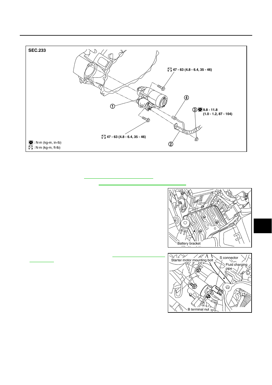
Removal and Installation
AKS004F2
REMOVAL
1.
Remove battery. Refer to
SC-8, "Removal and Installation"
.
2.
Remove air duct (inlet). Refer to
EM-16, "AIR CLEANER AND AIR DUCT"
3.
Remove battery bracket, using power tools.
4.
Remove fluid charging pipe. Refer to
.
5.
Disconnect “S” connector.
6.
Remove “B” terminal nut.
7.
Remove starter motor mounting bolts, using power tools.
8.
Remove starter motor upward from the vehicle.
INSTALLATION
Installation is the reverse order of removal.
CAUTION:
Be sure to tighten “B” terminal nut carefully.
1.
Starter motor
2.
B terminal harness
3.
B terminal nut
4.
S connector
PKIA2424E
PKIA2851E
PKIA2425E