Nissan Murano Z50 (2005 year). Manual - part 138


  Index      Manuals     Nissan Murano Z50 (2005 year) - Service and Repair Manual


Search            copyright infringement  


Content      ..     136      137      138      139     ..


Nissan Murano Z50 (2005 year). Manual - part 138


GI-4

PRECAUTIONS

Revision: 2005 August

2005 Murano

Precautions Necessary for Steering Wheel Rotation After Battery Disconnect

AAS000X5

NOTE:

This Procedure is applied only to models with Intelligent Key system and NVIS/IVIS (NISSAN/INFINITI
VEHICLE IMMOBILIZER SYSTEM - NATS).

Remove and install all control units after disconnecting both battery cables with the ignition knob in the

LOCK

 position.

Always use CONSULT-II to perform self-diagnosis as a part of each function inspection after finishing
work. If DTC is detected, perform trouble diagnosis according to self-diagnostic results.

For models equipped with the Intelligent Key system and NVIS/IVIS, an electrically controlled steering lock
mechanism is adopted on the key cylinder.
For this reason, if the battery is disconnected or if the battery is discharged, the steering wheel will lock and
steering wheel rotation will become impossible.
If steering wheel rotation is required when battery power is interrupted, follow the procedure below before
starting the repair operation.

OPERATION PROCEDURE

1.

Connect both battery cables.

NOTE:
Supply power using jumper cables if battery is discharged.

2.

Use the Intelligent Key or mechanical key to turn the ignition switch to the 

ACC

 position. At this time, the

steering lock will be released.

3.

Disconnect both battery cables. The steering lock will remain released and the steering wheel can be
rotated.

4.

Perform the necessary repair operation.

5.

When the repair work is completed, return the ignition switch to the 

LOCK

 position before connecting

the battery cables. (At this time, the steering lock mechanism will engage.)

6.

Perform a self-diagnosis check of all control units using CONSULT-II. 

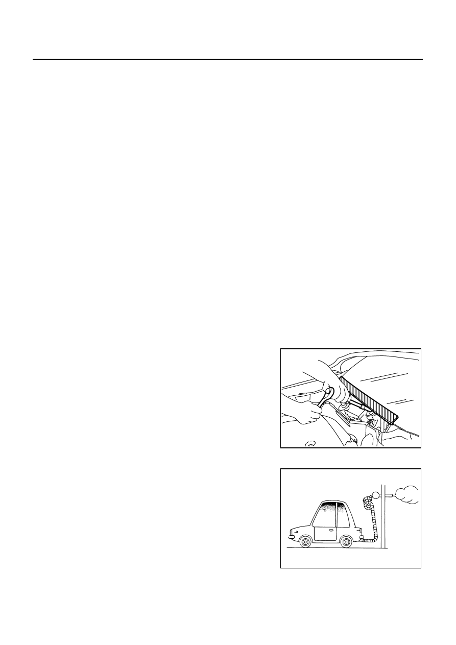
Precautions for Procedures without Cowl Top Cover

AAS000X6

When performing the procedure after removing cowl top cover, cover
the lower end of windshield with urethane, etc.

General Precautions

AAS000CJ

Do not operate the engine for an extended period of time without
proper exhaust ventilation.
Keep the work area well ventilated and free of any inflammable
materials. Special care should be taken when handling any
inflammable or poisonous materials, such as gasoline, refriger-
ant gas, etc. When working in a pit or other enclosed area, be
sure to properly ventilate the area before working with hazard-
ous materials.
Do not smoke while working on the vehicle.

PIIB3706J

SGI285

PRECAUTIONS

GI-5

C

D

E

F

G

H

I

J

K

L

M

B

GI

Revision: 2005 August

2005 Murano

Before jacking up the vehicle, apply wheel chocks or other tire
blocks to the wheels to prevent the vehicle from moving. After
jacking up the vehicle, support the vehicle weight with safety
stands at the points designated for proper lifting before working
on the vehicle.
These operations should be done on a level surface.

When removing a heavy component such as the engine or tran-
saxle/transmission, be careful not to lose your balance and drop
them. Also, do not allow them to strike adjacent parts, especially
the brake tubes and master cylinder.

Before starting repairs which do not require battery power:
Turn off ignition switch.
Disconnect the negative battery terminal.

If the battery terminals are disconnected, recorded memory of
radio and each control unit is erased.

To prevent serious burns:
Avoid contact with hot metal parts.
Do not remove the radiator cap when the engine is hot.

Dispose of drained oil or the solvent used for cleaning parts in
an appropriate manner.

Do not attempt to top off the fuel tank after the fuel pump nozzle
shuts off automatically.
Continued refueling may cause fuel overflow, resulting in fuel
spray and possibly a fire.

Clean all disassembled parts in the designated liquid or solvent
prior to inspection or assembly.

Replace oil seals, gaskets, packings, O-rings, locking washers, cotter pins, self-locking nuts, etc. with new
ones.

Replace inner and outer races of tapered roller bearings and needle bearings as a set.

Arrange the disassembled parts in accordance with their assembled locations and sequence.

Do not touch the terminals of electrical components which use microcomputers (such as ECM).
Static electricity may damage internal electronic components.

After disconnecting vacuum or air hoses, attach a tag to indicate the proper connection.

Use only the fluids and lubricants specified in this manual.

Use approved bonding agent, sealants or their equivalents when required.

Use hand tools, power tools (disassembly only) and recom-
mended special tools where specified for safe and efficient ser-
vice repairs.

When repairing the fuel, oil, water, vacuum or exhaust systems,
check all affected lines for leaks.

SGI231

SEF289H

SGI233

PBIC0190E

GI-6

PRECAUTIONS

Revision: 2005 August

2005 Murano

Before servicing the vehicle:
Protect fenders, upholstery and carpeting with appropriate cov-
ers.
Take caution that keys, buckles or buttons do not scratch paint.

WARNING:

To prevent ECM from storing the diagnostic trouble codes, do not carelessly disconnect the harness
connectors which are related to the engine control system and TCM (transmission control module)
system. The connectors should be disconnected only when working according to the WORK FLOW of
TROUBLE DIAGNOSES in EC and AT sections.

Precautions for Three Way Catalyst

AAS000CK

If a large amount of unburned fuel flows into the catalyst, the catalyst temperature will be excessively high. To
prevent this, follow the instructions.

Use unleaded gasoline only. Leaded gasoline will seriously damage the three way catalyst.

When checking for ignition spark or measuring engine compression, make tests quickly and only when
necessary.

Do not run engine when the fuel tank level is low, otherwise the engine may misfire, causing damage to
the catalyst.

Do not place the vehicle on flammable material. Keep flammable material off the exhaust pipe and the three
way catalyst.

Precautions for Fuel (Unleaded Premium Gasoline Recommended)

AAS000DK

Use unleaded regular gasoline with an octane rating of at least 87 AKI (Anti-Knock Index) number (Research
octane number 91).

For improved vehicle performance, NISSAN/INFINITI recommend the use of unleaded premium gasoline with
an octane rating of at least 91 AKI number (Research octane number 96).

CAUTION:

Do not use leaded gasoline. Using leaded gasoline will damage the three way catalyst. Do not use E-85
fuel (85% fuel ethanol, 15% unleaded gasoline) unless the vehicle is specifically designed for E-85 fuel
(i.e. Flexible Fuel Vehicle - FFV models). Using a fuel other than that specified could adversely affect
the emission control devices and systems, and could also affect the warranty coverage validity.

Precautions for Multiport Fuel Injection System or Engine Control System

AAS000CM

Before connecting or disconnecting any harness connector for
the multiport fuel injection system or ECM:
Turn ignition switch to “OFF” position.
Disconnect negative battery terminal.
Otherwise, there may be damage to ECM.

Before disconnecting pressurized fuel line from fuel pump to
injectors, be sure to release fuel pressure.

Be careful not to jar components such as ECM and mass air
flow sensor.

SGI234

SGI787

PRECAUTIONS

GI-7

C

D

E

F

G

H

I

J

K

L

M

B

GI

Revision: 2005 August

2005 Murano

Precautions for Hoses

AAS000CO

HOSE REMOVAL AND INSTALLATION

To prevent damage to rubber hose, do not pry off rubber hose
with tapered tool or screwdriver.

To reinstall the rubber hose securely, make sure that hose inser-
tion length and orientation is correct. (If tube is equipped with
hose stopper, insert rubber hose into tube until it butts up
against hose stopper.)

HOSE CLAMPING

If old rubber hose is re-used, install hose clamp in its original
position (at the indentation where the old clamp was). If there is
a trace of tube bulging left on the old rubber hose, align rubber
hose at that position. 

Discard old clamps; replace with new ones.

After installing plate clamps, apply force to them in the direction
of the arrow, tightening rubber hose equally all around.

Precautions for Engine Oils

AAS000CP

Prolonged and repeated contact with used engine oil may cause skin cancer. Try to avoid direct skin contact
with used oil.
If skin contact is made, wash thoroughly with soap or hand cleaner as soon as possible.

HEALTH PROTECTION PRECAUTIONS 

Avoid prolonged and repeated contact with oils, particularly used engine oils.

SMA019D

SMA020D

SMA021D

SMA022D

GI-8

PRECAUTIONS

Revision: 2005 August

2005 Murano

Wear protective clothing, including impervious gloves where practicable.

Do not put oily rags in pockets.

Avoid contaminating clothes, particularly underpants, with oil.

Heavily soiled clothing and oil-impregnated footwear should not be worn. Overalls must be cleaned regu-
larly.

First aid treatment should be obtained immediately for open cuts and wounds.

Use barrier creams, applying them before each work period, to help the removal of oil from the skin.

Wash with soap and water to ensure all oil is removed (skin cleansers and nail brushes will help). Prepa-
rations containing lanolin replace the natural skin oils which have been removed.

Do not use gasoline, kerosene, diesel fuel, gas oil, thinners or solvents for cleaning skin.

If skin disorders develop, obtain medical advice without delay.

Where practical, degrease components prior to handling.

Where there is a risk of eye contact, eye protection should be worn, for example, chemical goggles or face
shields; in addition an eye wash facility should be provided.

ENVIRONMENTAL PROTECTION PRECAUTIONS 

Dispose of used oil and used oil filters through authorized waste disposal contractors to licensed waste dis-
posal sites, or to the waste oil reclamation trade. If in doubt, contact the local authority for advice on disposal
facilities.
It is illegal to pour used oil on to the ground, down sewers or drains, or into water sources.
The regulations concerning pollution vary between regions.

Precautions for Air Conditioning 

AAS000CQ

Use an approved refrigerant recovery unit any time the air conditioning system must be discharged. Refer to
ATC/MTC section “HFC-134a (R-134a) Service Procedure”, “REFRIGERANT LINES” for specific instructions.

HOW TO USE THIS MANUAL

GI-9

C

D

E

F

G

H

I

J

K

L

M

B

GI

Revision: 2005 August

2005 Murano

HOW TO USE THIS MANUAL

PFP:00008

Description 

AAS000IN

This volume explains “Removal, Disassembly, Installation, Inspection and  Adjustment” and “Trouble Diag-
noses”.

Terms

AAS000IO

The captions WARNING  and CAUTION  warn you of steps that must be followed to prevent personal
injury and/or damage to some part of the vehicle.
WARNING indicates the possibility of personal injury if instructions are not followed.
CAUTION indicates the possibility of component damage if instructions are not followed.
BOLD TYPED STATEMENTS except WARNING  and CAUTION  give you helpful information.
Standard value:Tolerance at inspection and adjustment.
Limit value:The maximum or minimum limit value that should not be exceeded at inspection and adjust-
ment.

Units

AAS000IP

The UNITS  given in this manual are primarily expressed as the SI UNIT (International System of Unit),
and alternatively expressed in the metric system and in the yard/pound system.
Also with regard to tightening torque of bolts and nuts, there are descriptions both about range and about
the standard tightening torque.

“Example”
Range

Standard

Contents

AAS000IQ

ALPHABETICAL INDEX is provided at the end of this manual so that you can rapidly find the item and
page you are searching for.

A QUICK REFERENCE INDEX, a black tab (e.g. 

) is provided on the first page. You can quickly find

the first page of each section by matching it to the section's black tab.

THE CONTENTS are listed on the first page of each section.

THE TITLE is indicated on the upper portion of each page and shows the part or system.

THE PAGE NUMBER of each section consists of two or three letters which designate the particular sec-
tion and a number (e.g. “BR-5”).

THE SMALL ILLUSTRATIONS show the important steps such as inspection, use of special tools, knacks
of work and hidden or tricky steps which are not shown in the previous large illustrations.
Assembly, inspection and adjustment procedures for the complicated units such as the automatic tran-
saxle or transmission, etc. are presented in a step-by-step format where necessary.

Outer Socket Lock Nut

: 59 - 78 N·m (6.0 - 8.0 kg-m, 43 - 58 ft-lb)

Drive Shaft Installation Bolt

: 44.3 N·m (4.5 kg-m, 33 ft-lb)

GI-10

HOW TO USE THIS MANUAL

Revision: 2005 August

2005 Murano

Components

AAS000KT

THE LARGE ILLUSTRATIONS are exploded views (see the following) and contain tightening torques,
lubrication points, section number of the PARTS CATALOG  (e.g. SEC. 440) and other information neces-
sary to perform repairs.
The illustrations should be used in reference to service matters only. When ordering parts, refer to the
appropriate PARTS CATALOG .
Components shown in an illustration may be identified by a circled number. When this style of illustration
is used, the text description of the components will follow the illustration.

SYMBOLS

1.

Union bolt

2.

Copper washer

3.

Brake hose

4.

Cap

5.

Bleed valve

6.

Sliding pin bolt

7.

Piston seal

8.

Piston

9.

Piston boot

10.

Cylinder body

11.

Sliding pin

12.

Torque member mounting bolt

13.

Washer

14.

Sliding pin boot

15.

Bushing

16.

Torque member

17.

Inner shim cover

18.

Inner shim

19.

Inner pad

20.

Pad retainer

21.

Pad wear sensor

22.

Outer pad

23.

Outer shim

24.

Outer shim cover

1: PBC (Poly Butyl Cuprysil) grease 
or silicone-based grease

2: Rubber grease

: Brake fluid

Refer to GI section for additional symbol definitions.

SFIA2959E

SAIA0749E

HOW TO USE THIS MANUAL

GI-11

C

D

E

F

G

H

I

J

K

L

M

B

GI

Revision: 2005 August

2005 Murano

How to Follow Trouble Diagnoses

AAS000CW

DESCRIPTION

NOTICE:
Trouble diagnoses indicate work procedures required to diagnose problems effectively. Observe the following
instructions before diagnosing.

1.

Before performing trouble diagnoses, read the “Preliminary Check”, the “Symptom Chart” or the
“Work Flow”.

2.

After repairs, re-check that the problem has been completely eliminated.

3.

Refer to Component Parts and Harness Connector Location for the Systems described in each
section for identification/location of components and harness connectors.

4.

Refer to the Circuit Diagram for quick pinpoint check.
If you need to check circuit continuity between harness connectors in more detail, such as when a
sub-harness is used, refer to Wiring Diagram in each individual section and Harness Layout in PG
section for identification of harness connectors.

5.

When checking circuit continuity, ignition switch should be OFF.

6.

Before checking voltage at connectors, check battery voltage.

7.

After accomplishing the Diagnostic Procedures and Electrical Components Inspection, make sure
that all harness connectors are reconnected as they were.

HOW TO FOLLOW TEST GROUPS IN TROUBLE DIAGNOSES

1.

Work and diagnostic procedure
Start to diagnose a problem using procedures indicated in enclosed test groups.

2.

Questions and required results
Questions and required results are indicated in bold type in test group.
The meaning of are as follows:

SAIA0256E

GI-12

HOW TO USE THIS MANUAL

Revision: 2005 August

2005 Murano

3.

Symbol used in illustration
Symbols included in illustrations refer to measurements or procedures. Before diagnosing a problem,
familiarize yourself with each symbol. Refer to  "Connector Symbols" in GI Section and "KEY TO SYM-
BOLS SIGNIFYING MEASUREMENTS OR PROCEDURES" below.

4.

Action items
Next action for each test group is indicated based on result of each question. Test group number is shown
in the left upper portion of each test group.

HARNESS WIRE COLOR AND CONNECTOR NUMBER INDICATION

There are two types of harness wire color and connector number indication.

TYPE 1: Harness Wire Color and Connector Number are Shown in Illustration

Letter designations next to test meter probe indicate harness
wire color.

Connector numbers in a single circle (e.g. M33) indicate har-
ness connectors.

Connector numbers in a double circle (e.g. F211) indicate com-
ponent connectors.

a. Battery voltage 

 11 - 14V or approximately 12V

b. Voltage

: Approximately 0V 

 Less than 1V

AGI070

HOW TO USE THIS MANUAL

GI-13

C

D

E

F

G

H

I

J

K

L

M

B

GI

Revision: 2005 August

2005 Murano

TYPE 2: Harness Wire Color and Connector Number are Shown in Text

KEY TO SYMBOLS SIGNIFYING MEASUREMENTS OR PROCEDURES

SGI144A

SAIA0750E

GI-14

HOW TO USE THIS MANUAL

Revision: 2005 August

2005 Murano

SAIA0751E

HOW TO USE THIS MANUAL

GI-15

C

D

E

F

G

H

I

J

K

L

M

B

GI

Revision: 2005 August

2005 Murano

How to Read Wiring Diagrams

AAS000CX

CONNECTOR SYMBOLS 

Most of connector symbols in wiring diagrams are shown from the terminal side.

Connector symbols shown from the terminal side are enclosed
by a single line and followed by the direction mark.

Connector symbols shown from the harness side are enclosed
by a double line and followed by the direction mark.

Certain systems and components, especially those related to
OBD, may use a new style slide-locking type harness connector.
For description and how to disconnect, refer to PG section,
“Description”, “HARNESS CONNECTOR”.

Male and female terminals
Connector guides for male terminals are shown in black and
female terminals in white in wiring diagrams.

SAIA0257E

SGI363

GI-16

HOW TO USE THIS MANUAL

Revision: 2005 August

2005 Murano

SAMPLE/WIRING DIAGRAM - EXAMPL - 

For detail, refer to following “DESCRIPTION”.

SGI091A

HOW TO USE THIS MANUAL

GI-17

C

D

E

F

G

H

I

J

K

L

M

B

GI

Revision: 2005 August

2005 Murano

Optional Splice

DESCRIPTION 

SGI942

Num-

ber

Item

Description

1

Power condition

This shows the condition when the system receives battery positive voltage (can be oper-
ated).

2

Fusible link

The double line shows that this is a fusible link.

The open circle shows current flow in, and the shaded circle shows current flow out.

3

Fusible link/fuse loca-
tion

This shows the location of the fusible link or fuse in the fusible link or fuse box. For arrange-
ment, refer to PG section, POWER SUPPLY ROUTING.

4

Fuse

The single line shows that this is a fuse.

The open circle shows current flow in, and the shaded circle shows current flow out.

5

Current rating

This shows the current rating of the fusible link or fuse.

6

Connectors

This shows that connector E3 is female and connector M1 is male.

The G/R wire is located in the 1A terminal of both connectors.

Terminal number with an alphabet (1A, 5B, etc.) indicates that the connector is SMJ connec-
tor. Refer to PG section,  SMJ (SUPER MULTIPLE JUNCTION).

7

Optional splice

The open circle shows that the splice is optional depending on vehicle application.

8

Splice

The shaded circle shows that the splice is always on the vehicle.

9

Page crossing

This arrow shows that the circuit continues to an adjacent page.

The A will match with the A on the preceding or next page.

10

Common connector

The dotted lines between terminals show that these terminals are part of the same connector.

11

Option abbreviation

This shows that the circuit is optional depending on vehicle application.

12

Relay

This shows an internal representation of the relay. For details, refer to PG section, STAN-
DARDIZED RELAY.

13

Connectors

This shows that the connector is connected to the body or a terminal with bolt or nut.

GI-18

HOW TO USE THIS MANUAL

Revision: 2005 August

2005 Murano

14

Wire color

This shows a code for the color of the wire.

B = Black
W = White
R = Red
G = Green
L = Blue
Y = Yellow
LG = Light Green

BR = Brown
OR or O = Orange
P = Pink
PU or V (Violet) = Purple
GY or GR = Gray
SB = Sky Blue
CH = Dark Brown
DG = Dark Green

When the wire color is striped, the base color is given first, followed by the stripe color as shown 
below:
Example: L/W = Blue with White Stripe

15

Option description

This shows a description of the option abbreviation used on the page.

16

Switch

This shows that continuity exists between terminals 1 and 2 when the switch is in the A posi-
tion. Continuity exists between terminals 1 and 3 when the switch is in the B position.

17

Assembly parts

Connector terminal in component shows that it is a harness incorporated assembly.

18

Cell code

This identifies each page of the wiring diagram by section, system and wiring diagram page 
number.

19

Current flow arrow

Arrow indicates electric current flow, especially where the direction of standard flow (vertically 
downward or horizontally from left to right) is difficult to follow.

A double arrow “ 

 ” shows that current can flow in either direction depending on cir-

cuit operation.

20

System branch

This shows that the system branches to another system identified by cell code (section and 
system).

21

Page crossing

This arrow shows that the circuit continues to another page identified by cell code.

The C will match with the C on another page within the system other than the next or preced-
ing pages.

22

Shielded line

The line enclosed by broken line circle shows shield wire.

23

Component box in 
wave line

This shows that another part of the component is also shown on another page (indicated by 
wave line) within the system.

24

Component name

This shows the name of a component.

25

Connector number

This shows the connector number.

The letter shows which harness the connector is located in.

Example: M : main harness. For detail and to locate the connector, refer to PG section "Main 
Harness", “Harness Layout”. A coordinate grid is included for complex harnesses to aid in 
locating connectors.

26

Ground (GND)

The line spliced and grounded under wire color shows that ground line is spliced at the 
grounded connector.

27

Ground (GND)

This shows the ground connection. For detailed ground distribution information, refer to 
"Ground Distribution" in PG section.

28

Connector views

This area shows the connector faces of the components in the wiring diagram on the page.

29

Common component

Connectors enclosed in broken line show that these connectors belong to the same compo-
nent.

30

Connector color

This shows a code for the color of the connector. For code meaning, refer to wire color codes, 
Number 14 of this chart.

31

Fusible link and fuse 
box

This shows the arrangement of fusible link(s) and fuse(s), used for connector views of 
"POWER SUPPLY ROUTING" in PG section.
The open square shows current flow in, and the shaded square shows current flow out. 

32

Reference area

This shows that more information on the Super Multiple Junction (SMJ) and Joint Connectors 
(J/C) exists on the PG section. Refer to "Reference Area" for details.

Num-

ber

Item

Description

HOW TO USE THIS MANUAL

GI-19

C

D

E

F

G

H

I

J

K

L

M

B

GI

Revision: 2005 August

2005 Murano

Harness Indication 

Letter designations next to test meter probe indicate harness
(connector) wire color.

Connector numbers in a single circle M33 indicate harness con-
nectors.

Component Indication 

Connector numbers in a double circle F211 indicate component connectors.

Switch Positions 

Switches are shown in wiring diagrams as if the vehicle is in the “normal” condition.
A vehicle is in the “normal” condition when:

ignition switch is “OFF”,

doors, hood and trunk lid/back door are closed,

pedals are not depressed, and

parking brake is released.

AGI070

SGI860


Content      ..     136      137      138      139     ..