Nissan Murano Z50 (2005 year). Manual - part 51
TROUBLE DIAGNOSIS
BRC-35
[ABS]
C
D
E
G
H
I
J
K
L
M
A
B
BRC
Revision: 2005 August
2005 Murano
4.
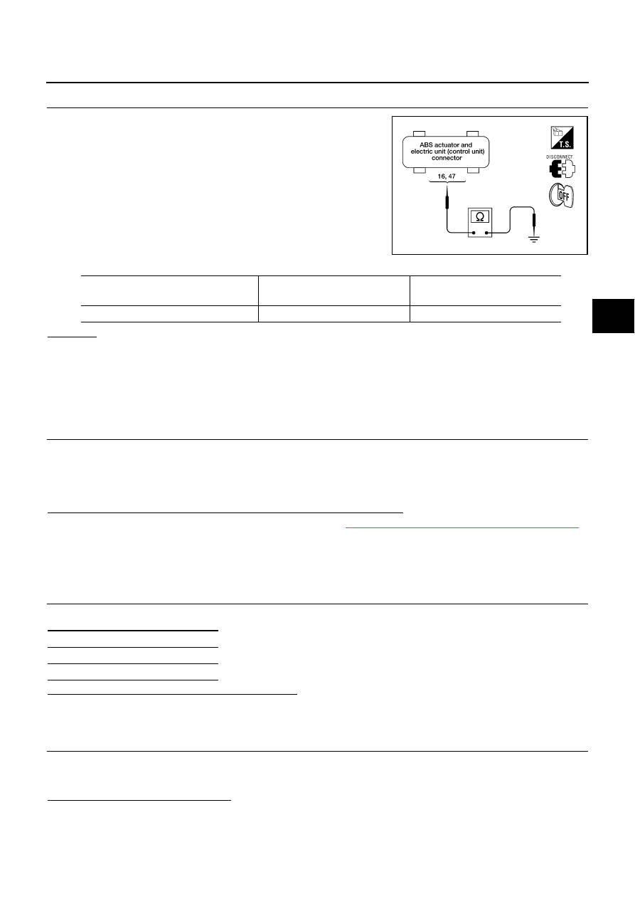
CHECK ABS ACTUATOR AND ELECTRIC UNIT (CONTROL UNIT) GROUND CIRCUIT
Check ABS actuator and electric unit (control unit) ground circuit.
OK or NG
OK
>> Perform self-diagnosis again. If the same results appear, replace ABS actuator and electric unit
(control unit).
NG
>> Open or short in harness. Repair or replace harness.
Inspection 4 CAN Communication Circuit
AFS00192
INSPECTION PROCEDURE
1.
CHECK CONNECTOR
1.
Turn ignition switch OFF, disconnect the ABS actuator and electric unit (control unit) connector, and check
the terminal for deformation, disconnection, looseness, and so on. If there is a malfunction, repair or
replace the terminal.
2.
Reconnect connector to perform self-diagnosis.
Is “CAN COMM CIRCUIT” displayed in the self-diagnosis display items?
YES
>> Print out the self-diagnostic results, and refer to
LAN-5, "Precautions When Using CONSULT-II"
NO
>> Connector terminal connector is loose, damaged, open, or shorted.
Inspection 5 Actuator Motor, Motor Relay, and Circuit
AFS001ZF
INSPECTION PROCEDURE
1.
CHECK SELF-DIAGNOSIS RESULT (1)
Check self-diagnosis results.
Is above displayed in self-diagnosis display items?
YES
>> GO TO 2.
NO
>> INSPECTION END
2.
CHECK SELF-DIAGNOSIS RESULT (2)
1.
Disconnect ABS actuator and electric unit (control unit) connector E24. Then reconnect it securely.
2.
Preform self-diagnosis again.
DO any self-diagnosis items appear?
YES
>> GO TO 3
NO
>> Poor connection. Repair or replace the applicable connector.
LFIA0152E
ABS actuator and electric unit
(Control unit)
Ground
Continuity
16 (B), 47 (B)
—
Yes
Self-diagnosis results
PUMP MOTOR
ACTUATOR RLY