Nissan Murano Z50 (2004 year). Manual - part 225


  Index      Manuals     Nissan Murano Z50 (2004 year) - Service and Repair Manual


Search            copyright infringement  


Content      ..     223      224      225      226     ..


Nissan Murano Z50 (2004 year). Manual - part 225


REAR WIPER AND WASHER SYSTEM

WW-37

C

D

E

F

G

H

I

J

L

M

A

B

WW

Revision: 2004 November

2004 Murano

REAR WIPER AND WASHER SYSTEM

PFP:28710

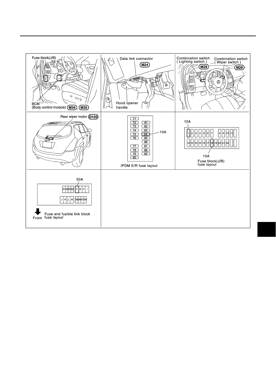
Components Parts and Harness Connector Location

AKS004X3

System Description

AKS004X4

Wiper switch (combination switch) is composed of a combination of 5 output terminals and 5 input termi-
nals. Terminal combination status is read by BCM (body control module) when switch is turned ON.

BCM (body control module) controls rear wiper ON and INT (intermittent) operation.

Power supplied all time

through 50 A fusible link (letter F, located in fusible link block)

to BCM (body control module) terminal 55

through 10 A fuse [No. 18, located in fuse block (J/B)]

to BCM (body control module) terminal 42.

When ignition switch ON or START position, power is supplied

through 10 A fuse [No. 1, located in fuse block (J/B)]

to BCM (body control module) terminal 38

through 10 A fuse [NO. 84, located in IPDM E/R (intelligent power distribution module engine room)]

through IPDM E/R (intelligent power distribution module engine room) terminal 44

to combination switch terminal 14.

Ground is supplied

to BCM (body control module) terminals 49 and 52

through grounds E14 and M78

to combination switch (wiper switch) terminal 12

through grounds M14 and M78.

PKIA6411E

WW-38

REAR WIPER AND WASHER SYSTEM

Revision: 2004 November

2004 Murano

REAR WIPER OPERATION

When wiper switch is in rear wiper ON position, BCM detect rear wiper ON signal by BCM wiper switch read-
ing function.
When BCM operates rear wiper motor, power is supplied 

through BCM terminal 70

to rear wiper motor 4.

Ground is supplied

to rear wiper motor terminal 2

through grounds B7 and B20. 

With power and ground supplied, the rear wiper operates.

INTERMITTENT OPERATION

The rear wiper motor operates the wiper arms at low speed approximately every 7 seconds.
When wiper switch is in rear wiper INT position, BCM detects rear wiper INT signal by BCM wiper switch read-
ing function (Refer to 

WW-7, "COMBINATION SWITCH READING FUNCTION"

 ).

When BCM operates rear wiper motor, power supplied

through BCM terminal 70

to rear wiper motor 4.

Ground is supplied

to rear wiper motor terminal 2 

through grounds B7 and B20.

With power and ground supplied, rear wiper operates at intermittent. 

AUTO STOP OPERATION

With rear wiper switch turned OFF, rear wiper motor will continue to operate until wiper arm reaches rear wiper
stopper.
Then wiper motor turns the other way and wiper arm moves once until wiper arm reaches stopper.

WASHER OPERATION

When wiper switch is in rear wiper washer position, BCM detects rear wiper washer signal by BCM wiper
switch reading function (Refer to 

WW-7, "COMBINATION SWITCH READING FUNCTION"

 ), and combination

switch (wiper switch) ground is supplied 
Power is supplied

through 10 A fuse [NO. 84, located in IPDM E/R (intelligent power distribution module engine room)]

to combination switch terminal 14

through combination switch (wiper switch) terminal 11

to front and rear washer motor terminal 2 

to front and rear washer motor terminal 1 

through combination switch (wiper switch) terminal 13

to combination switch (wiper switch) terminal 12

through grounds M14 and M78.

With ground supplied, front and rear washer motor is operated.
When BCM detects that front and rear washer motor has operated for. 0.4 seconds or linger, BCM operates
rear wiper motor at low speed. 
When BCM detects washer switch is OFF, low speed operation cycles approximately 3 times and then stops.

BCM WIPER SWITCH READING FUNCTION

Refer to 

WW-7, "COMBINATION SWITCH READING FUNCTION"

   in FRONT WIPER AND WASHER SYS-

TEM.

REAR WIPER AND WASHER SYSTEM

WW-39

C

D

E

F

G

H

I

J

L

M

A

B

WW

Revision: 2004 November

2004 Murano

Wiring Diagram — WIP/ R —

AKS004X5

TKWA1718E

WW-40

REAR WIPER AND WASHER SYSTEM

Revision: 2004 November

2004 Murano

TKWA1719E

REAR WIPER AND WASHER SYSTEM

WW-41

C

D

E

F

G

H

I

J

L

M

A

B

WW

Revision: 2004 November

2004 Murano

Terminals and Reference Values for BCM

AKS00ANI

Terminal No.

(Wire color)

Signal name

Measuring condition

Reference value

Ignition 

switch

Operation or condition

2 (R)

Combination switch input 5

ON

Lighting switch and wiper switch OFF

Wiper dial position 4

3 (P/L)

Combination switch input 4

ON

Lighting switch and wiper switch OFF

Wiper dial position 4

4 (R/G)

Combination switch input 3

ON

Lighting switch and wiper switch OFF

Wiper dial position 4

5 (R/B)

Combination switch input 2

ON

Lighting switch and wiper switch OFF

Wiper dial position 4

6 (R/W)

Combination switch input 1

32 (LG/B)

Combination switch output 5

ON

Lighting switch and wiper switch OFF

Wiper dial position 4

33 (G/Y)

Combination switch output 4

ON

Lighting switch and wiper switch OFF

Wiper dial position 4

34 (LG/R)

Combination switch output 3

ON

Lighting switch and wiper switch OFF

Wiper dial position 4

SKIA5291E

SKIA5292E

SKIA5291E

SKIA5292E

SKIA5291E

SKIA5292E

SKIA5291E

WW-42

REAR WIPER AND WASHER SYSTEM

Revision: 2004 November

2004 Murano

How to Proceed With Trouble Diagnosis

AKS004X7

1.

Confirm the symptoms and customer complaint.

2.

Understand operation description and function description. Refer to 

WW-37, "System Description"

 .

3.

Perform the Preliminary Check. Refer to 

WW-42, "Preliminary Check"

 .

4.

Check symptom and repair or replace the cause of malfunction.

5.

Does the warning chime operate normally? If YES: GO TO 6. If NO: GO TO 4.

6.

INSPECTION END

Preliminary Check

AKS004X8

CHECK POWER SUPPLY AND GROUND CIRCUIT

Inspection Procedure

1. 

CHECK FUSE

Check if wiper and washer fuse is blown.

Refer to 

WW-39, "Wiring Diagram — WIP/ R —"

 .

OK or NG

OK

>> GO TO 2.

NG

>> If fuse is blown, be sure to eliminate cause of malfunction before installing new fuse. Refer to 

PG-

3, "POWER SUPPLY ROUTING CIRCUIT"

 .

35 (G/B)

Combination switch output 2

ON

Lighting switch and wiper switch OFF

Wiper dial position 4

36 (L/W)

Combination switch output 1

38 (R)

Ignition switch (ON)

ON

Battery voltage

39 (L)

CAN  H

40 (Y)

CAN  L

42 (GR)

Battery power supply

OFF

Battery voltage

49 (B)

Ground

ON

Approx. 0 V

52 (B)

Ground

ON

Approx. 0 V

55 (W/B)

Battery power supply

OFF

Battery voltage

59 (O)

Rear wiper auto stop signal

ON

Wiper operating

Approx. 0 V

Wiper stopped

Battery voltage

70 (G)

Rear wiper motor output signal

ON

Wiper switch

OFF

Approx. 0 V

ON

Battery voltage

Terminal No.

(Wire color)

Signal name

Measuring condition

Reference value

Ignition 

switch

Operation or condition

SKIA5292E

Unit

Power source

Fuse and fusible link No.

Combination switch

Ignition ON or START

84

BCM

Battery

F

18

Ignition ON or START

1

REAR WIPER AND WASHER SYSTEM

WW-43

C

D

E

F

G

H

I

J

L

M

A

B

WW

Revision: 2004 November

2004 Murano

2. 

CHECK POWER SUPPLY CIRCUIT

1.

Turn ignition switch OFF.

2.

Disconnect BCM connector.

3.

Check voltage between BCM harness connector terminal and
ground.

OK or NG

OK

>> GO TO 3.

NG

>> Check harness for open or short between fuse, fusible link and BCM.

3. 

CHECK GROUND CIRCUIT 

Check continuity between BCM harness connector and ground.

OK or NG

OK

>> INSPECTION END

NG

>> Check harness ground circuit.

CONSULT-II Functions

AKS00ANJ

CONSULT-II can display each diagnostic item using the following diagnostic test modes: work support, self-
diagnostic results, data monitor and active test through data reception and command transmission via the
BCM CAN communication line.

CONSULT-II OPERATION

CAUTION:

If CONSULT-II is used with no connection of CONSULT-II CONVERTER, malfunctions might be
detected in self-diagnosis depending on control unit which carry out CAN communication. 

1.

With the ignition switch OFF, connect CONSULT-II and CON-
SULT-II CONVERTER to the data link connector, then turn the
ignition switch ON.

Terminals

Ignition switch position

(+)

(-)

OFF

ON

Connector

Terminal (Wire color)

M35

42 (GR)

Ground

Battery voltage

Battery voltage

M35

55 (W/B)

Battery voltage

Battery voltage

M34

38 (R)

0V

Battery voltage

PKIA5190E

Terminals

Continuity

Connector

Terminal (Wire color)

M35

49 (B)

Ground

Yes

52 (B)

PKIA5191E

BCM diagnosis position

Check item, Diagnosis mode

Description

Wiper

DATA MONITOR

Displays BCM input data in real time.

ACTIVE TEST

Device operation can be checked by applying a drive signal to device.

BCM

CAN DIAG SUPPORT MNTR

The result of transmit/receive diagnosis of CAN communication can be read.

PBIB1300E

WW-44

REAR WIPER AND WASHER SYSTEM

Revision: 2004 November

2004 Murano

2.

Touch “START (NISSAN BASED VHCL)”.

3.

Touch “BCM”.
If  “BCM” is not indicated, refer to 

GI-39, "CONSULT-II Data Link

Connector (DLC) Circuit"

 .

4.

Touch “WIPER”.

DATA MONITOR
Operation Procedure

1.

Touch “WIPER” on “SELECT TEST ITEM” screen.

2.

Touch “DATA MONITOR” on “SELECT DIAG MODE” screen.

3.

Touch either “ALL SIGNALS” or “SELECTION FROM MENU” on “DATA MONITOR” screen.

4.

Touch “START”.

5.

When “SELECTION FROM MENU” is selected, touched items to be monitored. If “ALL SIGNALS” is
selected, all items will be monitored.

6.

Touch “RECORDING START” while monitoring to record the status of the item being monitored. To stop
recording, touch “RECORDING STOP”.

Display Item List

SKIA3098E

PKIA6323E

PKIA6100E

ALL SIGNALS 

Monitors all the singal.

SELECTION FROM MENU

Selects and monitors individual signals.

Monitor item [operation or unit]

Display content

IGN ON SW

[ON/OFF]

Displays “ignition switch ON (ON)/Other OFF or ACC (OFF)” status as judged from ignition 
switch signal.

IGN SW CAN

[ON/OFF]

Displays “ignition switch ON (ON)/Other OFF or ACC (OFF)” status as judged from CAN com-
munication signal.

FR WIPER HI

[ON/OFF]

Displays “FRONT WIPER HI (ON)/Other (OFF)” status as judged from wiper switch signal.

REAR WIPER AND WASHER SYSTEM

WW-45

C

D

E

F

G

H

I

J

L

M

A

B

WW

Revision: 2004 November

2004 Murano

NOTE:
This item is displayed, but cannot monitor it.

ACTIVE TEST
Operation Procedure

1.

Touch “WIPER” on “SELECT TEST ITEM” screen.

2.

Touch “ACTIVE TEST” on “SELECT DIAG MODE” screen.

3.

Touch items to be tested, and check operation.

4.

During operation check, touching “STOP” deactivates operation.

Display Item List

Rear Wiper Does Not Operate

AKS004XA

1. 

CHECK FUSE AND FUSIBLE LINK

Check fuse No.1, 84 and fusible link No. F.

OK or NG

OK

>> GO TO 2.

NG

>> If fuse or fusible link is blown, be sure to eliminate cause of malfunction before installing new fuse

or fusible link, refer to 

PG-3, "POWER SUPPLY ROUTING CIRCUIT"

 .

2. 

REAR WIPER ACTIVE TEST

With CONSULT-ll

1.

Select “BCM” on CONSULT-II, and select “WIPER” on “SELECT
SYSTEM” screen.

2.

Select “ACTIVE TEST” on “SELECT DIAG MODE” screen.

3.

Select “REAR WIPER” on “SELECT TEST ITEM” screen.

4.

Confirm that rear wiper operates normally.

Without CONSULT-ll

GO TO 3.

Does rear wiper operate normally?

YES

>> GO TO 

LT-140, "Combination Switch Inspection"

 .

NO

>> GO TO 3.

FR WIPER LOW

[ON/OFF]

Displays “FRONT WIPER LOW (ON)/Other (OFF)” status as judged from wiper switch signal.

FR WIPER INT

[ON/OFF]

Displays “FRONT WIPER INT (ON)/Other (OFF)” status as judged from wiper switch signal.

FR WASHER SW

[ON/OFF]

Displays “FRONT WASHER Switch (ON)/Other (OFF)” status as judged from wiper switch sig-
nal.

INT VOLUME

[1 - 7]

Displays intermittent operation dial position setting (1 - 7) as judged from wiper switch signal.

FR WIPER STOP

[ON/OFF]

Displays “Stopped (ON)/Operating (OFF)” status as judged from the auto-stop signal.

VEHICLE SPEED

 [km/h] 

Displays vehicle speed status as judged from vehicle speed signal.

RR WIPER ON


[ON/OFF]

Displays “Rear Wiper ON (ON)/Other (OFF)” status as judged from wiper switch signal.

RR WIPER INT

[ON/OFF]

Displays “Rear Wiper INT (ON)/Other (OFF)” status as judged from wiper switch signal.

RR WASHER SW

[ON/OFF]

Displays “Rear Washer Switch (ON)/Other (OFF)” status as judged from wiper switch signal.

RR WIPER STOP

[ON/OFF]

Displays “Rear Wiper Stop (ON)/Other (OFF)” status, as judged from wiper switch signal.

RR WIPER STP2

NOTE

[OFF]

Monitor item [operation or unit]

Display content

Test item

Indication on CONSULT-II display

Description

Front wiper HI output

FRONT WIPER

With a certain operation (OFF, HI, LO, INT), the front wiper can be operated.

Rear wiper output

RR WIPER

Rear wiper can be operated by any ON-OFF operation.

SKIA3503E

WW-46

REAR WIPER AND WASHER SYSTEM

Revision: 2004 November

2004 Murano

3. 

CHECK CIRCUIT BETWEEN BCM AND REAR WIPER

1.

Turn ignition switch OFF.

2.

Disconnect BCM connector and rear wiper motor connector.

3.

Check continuity between BCM harness connector M36 termi-
nals 59 (O), 70 (G) and rear wiper motor harnes connector D103
terminals 3 (O), 4 (G).

4.

Check continuity between BCM harness connector M36 termi-
nals 59 (O), 70 (G) and ground.

OK or NG

OK

>> GO TO 4.

NG

>> Repair harness or connector.

4. 

CHECK REAR WIPER TO GROUND

Check continuity between rear wiper motor harness connector D103
terminal 2 (B) and ground.

OK or NG

OK

>> GO TO 5.

NG

>> Repair harness or connector.

5. 

CHECK BCM

1.

Connect BCM connector and rear wiper motor connector.

2.

Turn ignition switch ON.

3.

With rear wiper switch ON, check voltage between BCM har-
ness connector B14 terminal 59 (Y) and ground.

OK or NG

OK

>> Replace rear wiper motor.

NG

>> Replace BCM. Refer to 

BCS-14, "Removal and Installation of BCM"

 .

59 (O) - 3 (O)

: Continuity should exist.

70 (G) - 4 (G)

: Continuity should exist.

59 (O), 70 (G) - Ground

: Continuity should not exist.

PKIA5199E

2 (B) - Ground 

: Continuity should exist.

PKIA5200E

Terminals

Condition

Voltage

BCM(+)

(-)

Connector

Terminal (Wire color)

M36

59 (O)

Ground

Wiper stopped

Approx. 0V

Wiper operating

Battery voltage

PKIA5201E

REAR WIPER AND WASHER SYSTEM

WW-47

C

D

E

F

G

H

I

J

L

M

A

B

WW

Revision: 2004 November

2004 Murano

Rear Wiper Does Not Return to Stop Position

AKS00ANK

1. 

CHECK CIRCUIT BETWEEN BCM AND REAR WIPER (1)

With CONSULT-ll

Select “BCM” on CONSULT-II. With “WIPER” on “DATA MONITOR”,
confirm that “RR WIPER STOP” turns ON-OFF linked with wiper
operation.

Without CONSULT-ll

GO TO 2.

OK or NG

OK

>> Replace BCM. Refer to 

BCS-14, "Removal and Installa-

tion of BCM"

 .

NG

>> GO TO 2.

2. 

CHECK REAR WIPER AUTO STOP CIRCUIT

1.

Turn ignition switch OFF.

2.

Disconnect BCM connector and rear wiper motor connector.

3.

Check continuity between BCM harness connector M36 terminal
59 (O) and rear wiper motor harness connector D103 terminal 3
(O).

4.

Check continuity between BCM harness connector M36 terminal
59 (O) and ground.

5.

Check continuity between rear wiper motor harness connector
D103 terminal 2 (B) and ground.

OK or NG

OK

>> GO TO 3.

NG

>> Repair harness or connector.

SKIA5322E

59 (O) - 3 (O)

: Continuity should exist.

59 (O) - Ground

: Continuity should not exist.

PKIA5202E

2 (B) - Ground

: Continuity should exist.

PKIA5200E

WW-48

REAR WIPER AND WASHER SYSTEM

Revision: 2004 November

2004 Murano

3. 

CHECK CIRCUIT BETWEEN BCM AND REAR WIPER (2)

1.

Connect BCM connector and rear wiper motor connector.

2.

Turn ignition switch ON.

3.

Check voltage between rear wiper motor harness connector ter-
minal and ground while rear wiper motor is stopped and while it
is operating.

OK or NG

OK

>> Replace BCM. Refer to 

BCS-14, "Removal and Installation of BCM"

 .

NG

>> Replace rear wiper motor.

Only Rear Wiper ON Does Not Operate

AKS00ANL

Refer to 

LT-140, "Combination Switch Inspection"

 , and inspect it.

Only Rear Wiper INT Does Not Operate

AKS00ANM

Refer to 

LT-140, "Combination Switch Inspection"

 , and inspect it.

Wiper Does Not Wipe When Rear Washer Operates

AKS00ANN

Refer to 

LT-140, "Combination Switch Inspection"

 , and inspect it.

Rear Wipers Do Not Stop

AKS00ANO

1. 

CHECK CIRCUIT BETWEEN COMBINATION SWITCH AND BCM

With CONSULT-ll

Select “BCM” on CONSULT-II. With “WIPER” on “DATA MONITOR”,
confirm that “RR WIPER INT”, “RR WIPER ON”, and “RR WASHER
SW” turn ON-OFF according to wiper switch operation.

Without CONSULT-ll

Refer to 

LT-140, "Combination Switch Inspection"

 .

OK or NG

OK

>> Replace BCM. Refer to 

BCS-14, "Removal and Installa-

tion of BCM"

 .

NG

>> Check wiper Switch. Refer to 

LT-140, "Combination

Switch Inspection"

 .

Terminals

Condition

Voltage

Rear wiper motor (+)

(-)

Connector

Terminal (Wire color)

D103

3 (O)

Ground

Wiper stopped

Approx. 0V

Wiper operating

Battery voltage

PKIA5203E

SKIA5322E

REAR WIPER AND WASHER SYSTEM

WW-49

C

D

E

F

G

H

I

J

L

M

A

B

WW

Revision: 2004 November

2004 Murano

2. 

CHECK CIRCUIT BETWEEN BCM AND REAR WIPER (2), AND BETWEEN REAR WIPER AND 

GROUND

1.

Turn ignition switch OFF.

2.

Disconnect BCM connector and rear wiper motor connector.

3.

Check continuity between BCM connector M36 terminal 59 (O)
and rear wiper motor connector D103 terminal 3 (O).

4.

Check continuity between BCM connector M36 terminals 59(Y)
and Ground.

5.

Check continuity between rear wiper motor connector D103 ter-
minal 2 (B) and ground.

OK or NG

OK

>> GO TO 3.

NG

>> Repair harness or connector.

3. 

CHECK CIRCUIT BETWEEN BCM AND REAR WIPER (3)

1.

Connect BCM connector and rear wiper motor connector.

2.

Turn ignition switch ON.

3.

Check voltage between rear wiper motor harness connector ter-
minal and ground while rear wiper motor is stopped and while it
is operating.

OK or NG

OK

>> Replace BCM. Refer to 

BCS-14, "Removal and Installation of BCM"

 .

NG

>> Replace rear wiper motor.

Removal and Installation of Rear Wiper Arm, Adjustment of Wiper Arms Stop 
Location 

AKS00ANP

REMOVAL

1.

Operate wiper motor, and stop it at the auto stop position.

2.

Remove wiper arm cover and mounting nut, and then remove wiper arm from vehicle.

59 (O) - 3 (O)

: Continuity should exist.

59 (O) - Ground

: Continuity should not exist.

PKIA5202E

2 (B) - Ground

: Continuity should exist.

PKIA5200E

Terminals

Condition

Voltage

Rear wiper motor (+)

(-)

Connector

Terminal (Wire color)

D103

3 (O)

Ground

Wiper stopped

Approx. 0V

Wiper operating

Battery voltage

PKIA5203E

WW-50

REAR WIPER AND WASHER SYSTEM

Revision: 2004 November

2004 Murano

INSTALLATION

1.

Clean up the pivot area as illustrated. This will reduce possibility
of wiper arm looseness.

2.

Prior to wiper arm installation, turn on wiper switch to operate
wiper motor and then turn it “OFF” (Auto Stop).

3.

Lift the blade up and then set it down onto glass surface to set
the blade center to clearance “L” immediately before tightening
nut.

4.

Eject washer fluid. Turn on wiper switch to operate wiper motor
and then turn it “OFF”.

5.

Ensure that wiper blades stop within clearance “L”.

Tighten wiper arm nut to specified torque.

ADJUSTMENT

Refer to 

WW-50, "INSTALLATION"

 .

SEL024J

Clearance “L”

: 20.5 - 35.5 mm (0.807 - 1.398 in)

Rear wiper arm 
mounting nut

: 8.8 N·m (0.90 kg-m, 78 in-lb)

PKIA2561E

REAR WIPER AND WASHER SYSTEM

WW-51

C

D

E

F

G

H

I

J

L

M

A

B

WW

Revision: 2004 November

2004 Murano

Removal and Installation of Rear Wiper Motor 

AKS00ANQ

REMOVAL

1.

Remove wiper arm. Refer to 

WW-49, "Removal and Installation

of Rear Wiper Arm, Adjustment of Wiper Arms Stop Location"

 .

2.

Remove pivot cap.

3.

Remove back door finisher. Refer to 

EI-40, "BACK DOOR

TRIM"

   in “EI” section.

4.

Disconnect rear wiper motor connector.

5.

Remove rear wiper motor mounting bolts and remove rear
wiper motor.

INSTALLATION

1.

Attach pivot cap.

2.

Install rear wiper motor  to the vehicle.

3.

Connect rear wiper motor to the connector. Turn rear  wiper switch ON to operate rear wiper motor, then
turn wiper switch OFF (auto stop).

4.

Install back door finisher. Refer to 

EI-40, "BACK DOOR TRIM"

   in “EI” section.

5.

Attach wiper arm. Refer to 

WW-49, "Removal and Installation of Rear Wiper Arm, Adjustment of Wiper

Arms Stop Location"

 .

CAUTION:

Do not drop the wiper motor or cause it to contact other parts.

1.

Wiper blade

2.

Wiper arm

3.

Wiper arm cover

4.

Pivot cap

5.

Rear wiper motor

PKIA8652E

PKIA2563E

Rear wiper motor mounting  bolts

: 4.5 N·m (0.46 kg-m, 40 in-lb)

WW-52

REAR WIPER AND WASHER SYSTEM

Revision: 2004 November

2004 Murano

Removal and Installation of Rear Wiper Blade

AKS00ANR

REMOVAL

Remove the wiper blade as following the procedure below (as shown No.1 to 8 in the illustration).

CAUTION:

If the detaching force in the arrowed direction (see the illus-
tration) is less than 68.6N (7.0kg, 15.4lb), replace rear wiper
blade and rear wiper arm with new ones.

When replacing the rear wiper blade, blow air and remove
shaving of plastic or dust.

PKIA2693E

PKIA2692E


Content      ..     223      224      225      226     ..