Nissan Murano Z50 (2004 year). Manual - part 198


  Index      Manuals     Nissan Murano Z50 (2004 year) - Service and Repair Manual


Search            copyright infringement  


Content      ..     196      197      198      199     ..


Nissan Murano Z50 (2004 year). Manual - part 198


SUNROOF

RF-17

C

D

E

F

G

H

J

K

L

M

A

B

RF

Revision: 2004 November

2004 Murano

Work Flow

AIS002E7

1.

Check the symptom and customer's requests.

2.

Understand the outline of system. Refer to 

RF-10, "System Description"

 .

3.

According to the trouble diagnosis chart, repair or replace the cause of the malfunction. Refer to 

RF-20,

"Trouble Diagnosis Chart by Symptom"

 .

4.

Does power window system operate normally? If Yes, GO TO 5, If No, GO TO 3.

5.

INSPECTION END.

8

SB

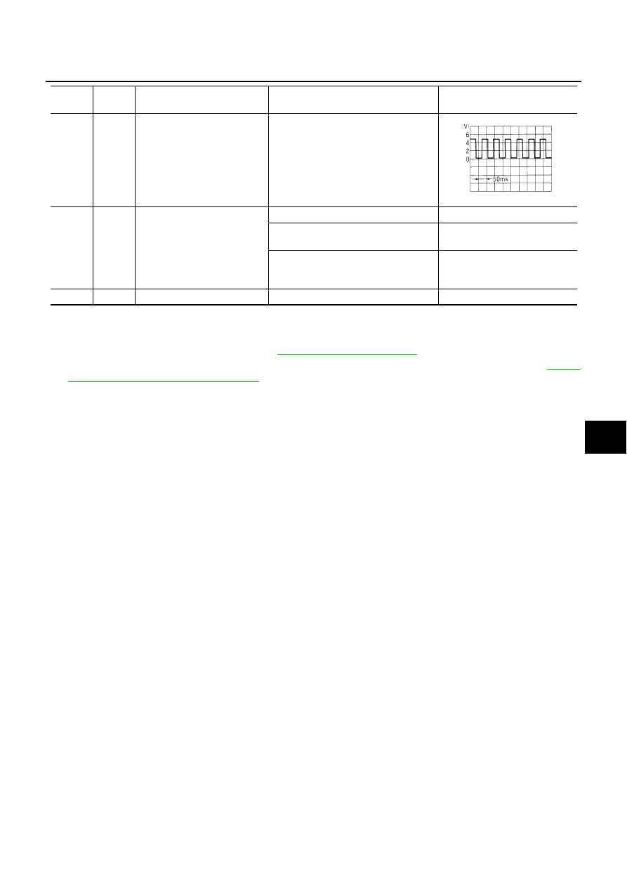
Vehicle speed signal (2-pulse)

Speedometer operated [When vehicle 
speed is approx.40km/ h (25MPH)]

9

W

RAP signal

Ignition switch ON

Battery voltage

Within 45 seconds after ignition switch is 
turned to OFF position

Battery voltage

Within approx.45 seconds after ignition 
switch OFF while front door LH or RH is 
open 

0

10

B

Ground

0

Termi-

nal

Wire 

color

Item

Condition

Voltage (V)

(Approx.)

ELF1080D

RF-18

SUNROOF

Revision: 2004 November

2004 Murano

CONSULT-II Function

AIS002E9

CAUTION:

If CONSULT-II is used with no connection of CONSULT-II CONVERTER, malfunction might be detected
in self-diagnosis depending on control unit which carry out CAN communication.

“RETAINED PWR”

1.

Turn ignition switch “OFF”.

2.

Connect “CONSULT-II” to the data link connector.

3.

Turn ignition switch “ON”.

4.

Touch “START (NISSAN BASED VHCL)”.

5.

Touch “BCM”.
If “BCM” is not indicated, go to Refer to “CONSULT-II Data Link
Connector (DLC) Circuit”.

6.

Touch “RETAINED PWR”.

PHIA0096E

MBIB0233E

LIIA0033E

LIIA0163E

SUNROOF

RF-19

C

D

E

F

G

H

J

K

L

M

A

B

RF

Revision: 2004 November

2004 Murano

7.

Select diagnosis mode. “DATA MONITOR”, “ACTIVE TEST” and
“WORK SUPPORT” are available.

Data Monitor

AIS002EA

Active Test

AIS002EB

Work Support 

AIS002EC

SEL274W

Monitored item

Description

IGN ON SW

Indicates [ON/OFF] condition of ignition switch.

DOOR SW-DR

Indicates [ON/OFF] condition of driver side door switch.

DDOR SW-AS

Indicates [ON/OFF] condition of passenger side door switch.

Test item

Description

RETAINED PWR

This test is able to supply RAP signal (power) from BCM to power window system and 
power sunroof system. Those systems can be operated when turning on “RETAINED 
PWR” on CONSULT-II screen even if the ignition switch is turned OFF.

NOTE:
During this test, CONSULT-II can be operated with ignition switch in “OFF” 
position.“RETAINED PWR” should be turned “ON” or “OFF” on CONLUST-II 
screen when ignition switch in ON. Then turn ignition switch OFF for checking 
retained power operation. CONSULT-II might be stuck if “RETAINED PWR” is 
turned to “ON” or “OFF” on CONSULT-II screen when ignition switch is OFF.

Work item

Description

RETAINED PWR SET

RAP signal’s power supply period can be changed by mode setting. Selects RAP sig-
nal’s power supply period between two steps.

MODE 1 (45 sec.) / MODE 2 (OFF) / MODE 3 (2 min.)

RF-20

SUNROOF

Revision: 2004 November

2004 Murano

Trouble Diagnosis Chart by Symptom

AIS002ED

BCM Power Supply and Ground Circuit Check

AIS00350

First perform the “SELF-DIAG RESULTS” in “BCM” with CONSULT-II, then perform the each trouble
diagnosis of malfunction system indicated “SELF-DIAG RESULTS” of “BCM”. Refer to 

BCS-14, "CAN

Communication Inspection Using CONSULT-II (Self-Diagnosis)"

 .

1. 

CHECK FUSE 

Check 10A fuse [No.1, located in fuse block (J/B)]

Check 10A fuse [No. 18, located in fuse block (J/B)]

Check 50A fusible link (letter F   located in the fuse and fusible link box).

NOTE:
Refer to 

RF-10, "Component Parts and Harness Connector Location"

 .

OK or NG

OK

>> GO TO 2.

NG

>> If fuse is blown, be sure to eliminate cause of malfunction before installing new fuse. Refer to 

PG-

3, "POWER SUPPLY ROUTING CIRCUIT"

Symptom

Diagnostic procedure and repair order

Refer to page

Sunroof does not operate.

1. BCM power supply and ground circuit check.

RF-20

2. Sunroof motor assembly power supply and 
ground circuit check.

RF-22

3. Sunroof switch circuit check 9.

RF-29

4. Replace the sunroof motor assembly.

RF-42

Sunroof alone does not go to full close position.

1. Sunroof switch circuit check 1.

RF-24

Sunroof alone does not go to slide position 1.

1. Sunroof switch circuit check 2.

RF-25

Sunroof alone does not go to slide position 2.

1. Sunroof switch circuit check 3.

RF-25

Sunroof alone does not go to slide position 3.

1. Sunroof switch circuit check 4.

RF-26

Sunroof alone does not go to slide position 4.

1. Sunroof switch circuit check 5.

RF-27

Sunroof alone does not go to full open position.

1. Sunroof switch circuit check 6.

RF-27

Sunroof alone does not operate tilt up.

1. Sunroof switch circuit check 7.

RF-28

Sunroof alone does not operate tilt down.

1. Sunroof switch circuit check 8.

RF-29

Sunroof does not go to slide position 2, 3 and 4.

1. Sunroof switch circuit check 10.

RF-31

Sunroof does not go to full closed and slide position 1, 2.

1. Sunroof switch circuit check 11.

RF-32

Sunroof does not go to full close, full open and slide posi-
tion 4.

1. Sunroof switch circuit check 12.

RF-33

Retained power operation does not operate properly.

1. Check the retained power operation mode setting.

RF-18

2. Door switch check.

RF-34

3. BCM check.

RF-23

4. Replace sunroof motor assembly.

RF-42

Motor does not stop at the sunroof fully -open or fully- 
closed position.

1. Initialization procedure check.

RF-12

2. Replace the sunroof motor assembly.

RF-42

Sunroof does not do the interruption detection.

1. Replace the sunroof motor assembly.

RF-42

SUNROOF

RF-21

C

D

E

F

G

H

J

K

L

M

A

B

RF

Revision: 2004 November

2004 Murano

2. 

CHECK POWER SUPPLY CIRCUIT

1.

Turn ignition switch ON.

2.

Check voltage between BCM connectors M34, M35 terminals 38, 42, 55 and ground.

OK or NG

OK

>> GO TO 3.

NG

>> Check BCM power supply circuit for open or short.

3. 

CHECK GROUND CIRCUIT

1.

Turn ignition switch OFF.

2.

Disconnect BCM connector.

3.

Check continuity between BCM connector M35 terminals 52 and ground.

OK or NG

OK

>> BCM power supply and ground circuit is OK.

NG

>> Check BCM ground circuit for open or short.

38 (R) – Ground

: Battery voltage

42 (GR) – Ground

: Battery voltage

55 (W/B) – Ground

: Battery voltage

PIIA6160E

52 (B) –- Ground

: Continuity should exist.

PIIA9131E

RF-22

SUNROOF

Revision: 2004 November

2004 Murano

Sunroof Motor Assembly Power Supply and Ground Circuit Check

AIS002EE

1. 

CHECK POWER SUPPLY CIRCUIT

1.

Turn ignition switch ON.

2.

Check voltage between sunroof motor assembly connector R6 terminals 7, 9 and ground.

OK or NG

OK

>> GO TO 2.

NG

>> GO TO 3.

2. 

CHECK GROUND CIRCUIT 

1.

Turn ignition switch OFF.

2.

Disconnect sunroof motor assembly connector.

3.

Check continuity between sunroof motor assembly connector R6 terminal 10 and ground.

OK or NG

OK

>> Sunroof motor assembly power supply and ground cir-

cuit are OK. Further inspection is necessary. Refer to
symptom chart.

NG

>> Repair or replace harness.

3. 

CHECK SUNROOF MOTOR ASSEMBLY POWER SUPPLY CIRCUIT 

1.

Turn ignition switch OFF.

2.

Disconnect BCM and sunroof motor assembly connector.

3.

Check continuity between BCM connector M35 terminals 53, 54 and sunroof motor assembly connector
R6 terminals 7, 9.

4.

Check continuity between BCM connector M35 terminals 53, 54
and ground.

OK or NG

OK

>> GO TO 4.

NG

>> Repair or replace harness.

7 (L) – Ground

: Battery voltage

9 (W) – Ground

: Battery voltage

PIIA4533E

10 (B) – Ground

: Continuity should exist.

PIIA4534E

53 (W/L) – 9 (W)

: Continuity should exist.

54 (W/R) – 7 (L)

: Continuity should exist.

53 (W/L) – Ground

: Continuity should not exist.

54 (W/R) – Ground

: Continuity should not exist.

PIIA9715E

SUNROOF

RF-23

C

D

E

F

G

H

J

K

L

M

A

B

RF

Revision: 2004 November

2004 Murano

4. 

CHECK BCM OUTPUT SIGNAL

1.

Connect BCM connector.

2.

Turn ignition switch ON.

3.

Check voltage between BCM connector M35 terminals 53, 54 and ground.

OK or NG

OK

>> Check condition of the harness and the connector.

NG

>> Replace BCM.

BCM Check

AIS002K8

1. 

CHECK RETAINED POWER INPUT SIGNAL

Check voltage between sunroof motor assembly connector and ground.

OK or NG

OK

>> Retained power operation input signal is OK.

NG

>> GO TO 2.

2. 

CHECK HARNESS CONTINUITY 

1.

Turn ignition switch OFF.

2.

Disconnect BCM and sunroof motor assembly connector.

3.

Check continuity between BCM connector M35 terminal 53 and
sunroof motor assembly connector R6 terminal 9.

4.

Check continuity between BCM connector M35 terminal 53 and
ground.

OK or NG

OK

>> GO TO 3.

NG

>> Repair or replace harness between BCM and sunroof

motor assembly.

53 (W/L) – Ground

: Battery voltage

54 (W/R) – Ground

: Battery voltage

PIIA6154E

Con-

nector

Terminals (Wire color)

Condition

Voltage (V)

(Approx.)

(+)

(–)

R6

9 (W)

Ground

Ignition switch ON 

Battery voltage

Within 45 seconds after igni-
tion switch in turned to OFF 
position

Battery voltage

Within approx.45 seconds 
after ignition switch OFF while 
front door LH or RH is open

0

PIIA4506E

53 (W/L) – 9 (W)

: Continuity should exist.

53 (W/L) – Ground

: Continuity should not exist.

PIIA9716E

RF-24

SUNROOF

Revision: 2004 November

2004 Murano

3. 

CHECK RETAINED POWER OUTPUT SIGNAL

1.

Connect BCM connector.

2.

Check voltage between BCM connector and ground.

OK or NG

OK

>> Check condition of the harness and the connector.

NG

>> Replace BCM.

Sunroof Switch Circuit Check 1

AIS002K9

1. 

CHECK SUNROOF SWITCH

1.

Turn ignition switch OFF.

2.

Disconnect sunroof switch connector.

3.

Check continuity between sunroof switch terminals 2, 3 and 6.

OK or NG

OK

>> GO TO 2.

NG

>> Replace sunroof switch.

2. 

CHECK SUNROOF SWITCH OUTPUT SINGAL

1.

Connect sunroof motor connector.

2.

Turn ignition switch ON.

3.

Check voltage between sunroof motor assembly connector and
ground.

OK or NG

OK

>> Replace sunroof motor assembly.

NG

>> Check the condition of the harness and the connector.

Con-

nector

Terminals (Wire color)

Condition

Voltage (V)

(Approx.)

(+)

(–)

M35

53 (W/L)

Ground

Ignition switch ON 

Battery voltage

Within 45 seconds after igni-
tion switch in turned to OFF 
position

Battery voltage

Within approx.45 seconds 
after ignition switch OFF while 
front door LH or RH is open

0

PIIA9717E

Terminals

Condition

Continuity 

2
3

6

Slide switch
FULL CLOSE position

Yes

Other than above

No

PIIA4511E

Connector

Terminals (Wire color)

Condition

Voltage (V)

(Approx.)

(+)

(–)

R6

3 (R)
4 (Y)

Ground

Slide switch
FULL CLOSE position 

0

Other than above 

Battery voltage

PIIA4509E

SUNROOF

RF-25

C

D

E

F

G

H

J

K

L

M

A

B

RF

Revision: 2004 November

2004 Murano

Sunroof Switch Circuit Check 2

AIS002KA

1. 

CHECK SUNROOF SWITCH

1.

Turn ignition switch OFF.

2.

Disconnect sunroof switch connector.

3.

Check continuity between sunroof switch terminals 2 and 6.

OK or NG

OK

>> GO TO 2.

NG

>> Replace sunroof switch.

2. 

CHECK SUNROOF SWITCH OUTPUT SINGAL

1.

Connect sunroof switch connector.

2.

Turn ignition switch ON.

3.

Check voltage between sunroof motor assembly connector and
ground.

OK or NG

OK

>> Replace sunroof motor assembly.

NG

>> Check the condition of the harness and the connector.

Sunroof Switch Circuit Check 3

AIS002KB

1. 

CHECK SUNROOF SWITCH

1.

Turn ignition switch OFF.

2.

Disconnect sunroof switch connector.

3.

Check continuity between sunroof switch terminals 1, 2 and 6.

OK or NG

OK

>> GO TO 2.

NG

>> Replace sunroof switch.

Terminals

Condition

Continuity 

2

6

Slide switch
SLIDE POSITION 1

Yes

Other than above

No

PIIA4514E

Connector

Terminals (Wire color)

Condition

Voltage (V)

(Approx.)

(+)

(–)

R6

3 (R)

Ground

Slide switch
SLIDE POSITION 1 

0

Other than above 

Battery voltage

PIIA4512E

Terminals

Condition

Continuity 

1
2

6

Slide switch
FULL CLOSE position

Yes

Other than above

No

PIIA4517E

RF-26

SUNROOF

Revision: 2004 November

2004 Murano

2. 

CHECK SUNROOF SWITCH OUTPUT SINGAL

1.

Connect sunroof switch connector.

2.

Turn ignition switch ON.

3.

Check voltage between sunroof motor assembly connector and
ground.

OK or NG

OK

>> Replace sunroof motor assembly.

NG

>> Check the condition of the harness and the connector.

Sunroof Switch Circuit Check 4

AIS002KC

1. 

CHECK SUNROOF SWITCH

1.

Turn ignition switch OFF.

2.

Disconnect sunroof switch connector.

3.

Check continuity between sunroof switch terminals 1 and 6.

OK or NG

OK

>> GO TO 2.

NG

>> Replace sunroof switch.

2. 

CHECK SUNROOF SWITCH OUTPUT SINGAL

1.

Connect sunroof switch connector.

2.

Turn ignition switch ON.

3.

Check voltage between sunroof motor assembly connector and
ground.

OK or NG

OK

>> Replace sunroof motor assembly.

NG

>> Check the condition of the harness and the connector.

Connector

Terminals (Wire color)

Condition

Voltage (V)

(Approx.)

(+)

(–)

R6

2 (G)
3 (R)

Ground

Slide switch
SLIDE POSITION 2 

0

Other than above 

Battery voltage

PIIA4515E

Terminals

Condition

Continuity 

1

6

Slide switch
SLIDE POSITION 3

Yes

Other than above

No

PIIA4520E

Connector

Terminals (Wire color)

Condition

Voltage (V)

(Approx.)

(+)

(–)

R6

2 (G)

Ground

Slide switch
SLIDE POSITION 3

0

Other than above 

Battery voltage

PIIA4518E

SUNROOF

RF-27

C

D

E

F

G

H

J

K

L

M

A

B

RF

Revision: 2004 November

2004 Murano

Sunroof Switch Circuit Check 5

AIS002KD

1. 

CHECK SUNROOF SWITCH

1.

Turn ignition switch OFF.

2.

Disconnect sunroof switch connector.

3.

Check continuity between sunroof switch terminals 1, 3 and 6.

OK or NG

OK

>> GO TO 2.

NG

>> Replace sunroof switch.

2. 

CHECK SUNROOF SWITCH OUTPUT SINGAL

1.

Connect sunroof switch connector.

2.

Turn ignition switch ON.

3.

Check voltage between sunroof motor assembly connector and
ground.

OK or NG

OK

>> Replace sunroof motor assembly.

NG

>> Check the condition of the harness and the connector.

Sunroof Switch Circuit Check 6

AIS002KE

1. 

CHECK SUNROOF SWITCH

1.

Turn ignition switch OFF.

2.

Disconnect sunroof switch connector.

3.

Check continuity between sunroof switch terminals 3 and 6.

OK or NG

OK

>> GO TO 2.

NG

>> Replace sunroof switch.

Terminals

Condition

Continuity 

1
3

6

Slide switch
FULL CLOSE position

Yes

Other than above

No

PIIA4523E

Connector

Terminals (Wire color)

Condition

Voltage (V)

(Approx.)

(+)

(–)

R6

2 (G)

4 (Y)

Ground

Slide switch
SLIDE POSITION 4 

0

Other than above 

Battery voltage

PIIA4521E

Terminals

Condition

Continuity 

3

6

Slide switch
FULL OPEN position

Yes

Other than above

No

PIIA4526E

RF-28

SUNROOF

Revision: 2004 November

2004 Murano

2. 

CHECK SUNROOF SWITCH OUTPUT SINGAL

1.

Connect sunroof switch connector.

2.

Turn ignition switch ON.

3.

Check voltage between sunroof motor assembly connector and
ground.

OK or NG

OK

>> Replace sunroof motor assembly.

NG

>> Check the condition of the harness and the connector.

Sunroof Switch Circuit Check 7

AIS002KF

1. 

CHECK SUNROOF SWITCH

1.

Turn ignition switch OFF.

2.

Disconnect sunroof switch connector.

3.

Check continuity between sunroof switch terminals 5 and 6.

OK or NG

OK

>> GO TO 2.

NG

>> Replace sunroof switch.

2. 

CHECK SUNROOF SWITCH OUTPUT SINGAL

1.

Connect sunroof switch connector.

2.

Turn ignition switch ON.

3.

Check voltage between sunroof motor assembly connector and
ground.

OK or NG

OK

>> Replace sunroof motor assembly.

NG

>> Check the condition of the harness and the connector.

Connector

Terminals (Wire color)

Condition

Voltage (V)

(Approx.)

(+)

(–)

R6

4 (Y)

Ground

Slide switch
FULL OPEN position 

0

Other than above 

Battery voltage

PIIB0505E

Terminals

Condition

Continuity 

5

6

Tilt switch
UP position

Yes

Other than above

No

PIIA4529E

Connector

Terminals (Wire color)

Condition

Voltage (V)

(Approx.)

(+)

(–)

R6

1 (V)

Ground

Tilt switch
UP position 

0

Other than above 

Battery voltage

PIIA4527E

SUNROOF

RF-29

C

D

E

F

G

H

J

K

L

M

A

B

RF

Revision: 2004 November

2004 Murano

Sunroof Switch Circuit Check 8

AIS002KG

1. 

CHECK SUNROOF SWITCH

1.

Turn ignition switch OFF.

2.

Disconnect sunroof switch connector.

3.

Check continuity between sunroof switch terminals 4 and 6.

OK or NG

OK

>> GO TO 2.

NG

>> Replace sunroof switch.

2. 

CHECK SUNROOF SWITCH OUTPUT SINGAL

1.

Connect sunroof switch connector.

2.

Turn ignition switch ON.

3.

Check voltage between sunroof motor assembly connector and
ground.

OK or NG

OK

>> Replace sunroof motor assembly.

NG

>> Check the condition of the harness and the connector.

Sunroof Switch Circuit Check 9

AIS002KH

1. 

CHECK SUNROOF MOTOR OUTPUT SIGNAL

1.

Turn ignition switch OFF.

2.

Disconnect sunroof motor switch connector.

3.

Turn ignition switch ON.

4.

Check voltage between sunroof motor assembly connector R6
terminals 1, 2, 3, 4, 5 and ground.

OK or NG

OK

>> GO TO 2

NG

>> Replace sunroof motor assembly.

Terminals

Condition

Continuity 

4

6

Tilt switch
UP position

Yes

Other than above

No

PIIA4532E

Connector

Terminals (Wire color)

Condition

Voltage (V)

(Approx.)

(+)

(–)

R6

5 (O)

Ground

Tilt switch
DOWN position 

0

Other than above 

Battery voltage

PIIA4530E

1 (V) – Ground

: Battery voltage

2 (G) – Ground

: Battery voltage

3 (R) – Ground

: Battery voltage

4 (Y) – Ground

: Battery voltage

5 (O) – Ground

: Battery voltage

PIIA4536E

RF-30

SUNROOF

Revision: 2004 November

2004 Murano

2. 

CHECK HARNESS CONTINUITY 

1.

Turn ignition switch OFF.

2.

Disconnect sunroof switch connector.

3.

Check continuity between sunroof motor assembly connector
R6 terminals 1, 2, 3, 4, 5 and sunroof switch connector R5 termi-
nals 1, 2, 3, 4, 5.

4.

Check continuity between sunroof motor assembly connector
R6 terminals 1, 2, 3, 4, 5 and ground.

OK or NG

OK

>> GO TO 3.

NG

>> Repair or replace harness.

3. 

CHECK GROUND CIRCUIT

Check continuity between sunroof switch connector R5 terminal 6
and ground.

OK or NG

OK

>> Check condition of the harness and the connector.

NG

>> Repair or replace harness.

1 (V) – 5 (V)

: Continuity should exist.

2 (G) – 1 (G)

: Continuity should exist.

3 (R) – 2 (R)

: Continuity should exist.

4 (Y) – 3 (Y)

: Continuity should exist.

5 (O) – 4 (O)

: Continuity should exist.

1 (V) – Ground

: Continuity should not exist.

2 (G) – Ground

: Continuity should not exist.

3 (R) – Ground

: Continuity should not exist.

4 (Y) – Ground

: Continuity should not exist.

5 (O) – Ground

: Continuity should not exist.

PIIA4537E

6 (B) – Ground

: Continuity should exist.

PIIA4538E

SUNROOF

RF-31

C

D

E

F

G

H

J

K

L

M

A

B

RF

Revision: 2004 November

2004 Murano

Sunroof Switch Circuit Check 10

AIS00351

1. 

CHECK SUNROOF SWITCH OUTPUT SINGAL

1.

Turn ignition switch ON.

2.

Check voltage between sunroof motor assembly connector and
ground.

OK or NG

OK

>> Replace sunroof motor assembly.

NG

>> GO TO 2.

2. 

CHECK HARNESS CONTINUITY

1.

Turn ignition switch OFF.

2.

Disconnect sunroof motor assembly and sunroof switch connector.

3.

Check continuity between sunroof motor assembly connector R6 terminal 2 and sunroof switch connector
R5 terminal 1.

OK or NG

OK

>> GO TO 3.

NG

>> Repair or replace harness between sunroof motor

assembly and sunroof switch.

3. 

CHECK SUNROOF SWITCH

Check continuity between sunroof switch terminals 1 and 6.

OK or NG

OK

>> Check the condition of the harness and the connector.

NG

>> Replace sunroof switch.

Connector

Terminals (Wire color)

Condition

Voltage (V)

(Approx.)

(+)

(–)

R6

2 (G)

Ground

Slide switch
SLIDE POSITION 2
SLIDE POSITION 3
SLIDE POSITION 4

0

Other than above 

Battery voltage

PIIA4518E

2 (G) – 1 (G)

: Continuity should exist.

PIIA4519E

Terminals

Condition

Continuity 

1

6

Slide switch
SLIDE POSITION 2
SLIDE POSITION 3
SLIDE POSITION 4

Yes

Other than above

No

PIIA4520E

RF-32

SUNROOF

Revision: 2004 November

2004 Murano

Sunroof Switch Circuit Check 11

AIS00352

1. 

CHECK SUNROOF SWITCH OUTPUT SINGAL

1.

Turn ignition switch ON.

2.

Check voltage between sunroof motor assembly connector and
ground.

OK or NG

OK

>> Replace sunroof motor assembly.

NG

>> GO TO 2.

2. 

CHECK HARNESS CONTINUITY

1.

Turn ignition switch OFF.

2.

Disconnect sunroof motor assembly and sunroof switch connector.

3.

Check continuity between sunroof motor assembly connector R6 terminal 3 and sunroof switch connector
R5 terminal 2.

OK or NG

OK

>> GO TO 3.

NG

>> Repair or replace harness between sunroof motor

assembly and sunroof switch.

3. 

CHECK SUNROOF SWITCH

Check continuity between sunroof switch terminals 2 and 6.

OK or NG

OK

>> Check the condition of the harness and the connector.

NG

>> Replace sunroof switch.

Connector

Terminals (Wire color)

Condition

Voltage (V)

(Approx.)

(+)

(–)

R6

3 (R)

Ground

Slide switch
FULL CLOSE
SLIDE POSITION 1
SLIDE POSITION 2

0

Other than above 

Battery voltage

PIIA4512E

3 (R) – 2 (R)

: Continuity should exist.

PIIA4513E

Terminals

Condition

Continuity 

2

6

Slide switch
FULL CLOSE
SLIDE POSITION 1
SLIDE POSITION 2

Yes

Other than above

No

PIIA4514E


Content      ..     196      197      198      199     ..