Nissan Murano Z50 (2004 year). Manual - part 172
CAN SYSTEM (TYPE 16)
LAN-569
[CAN]
C
D
E
F
G
H
I
J
L
M
A
B
LAN
Revision: 2004 November
2004 Murano
AWD Control Unit Circuit Check
AKS00A8H
1.
CHECK CONNECTOR
1.
Turn ignition switch OFF.
2.
Disconnect the negative battery terminal.
3.
Check terminals and connector of AWD control unit for damage, bend and loose connection (control unit
side and harness side).
OK or NG
OK
>> GO TO 2.
NG
>> Repair terminal or connector.
2.
CHECK HARNESS FOR OPEN CIRCUIT
1.
Disconnect AWD control unit connector.
2.
Check resistance between AWD control unit harness connector
E111 terminals 8 (L) and 16 (Y).
OK or NG
OK
>> Replace AWD control unit.
NG
>> Repair harness between AWD control unit and IPDM E/
R.
ABS Actuator and Electric Unit (Control Unit) Circuit Check
AKS00A8I
1.
CHECK CONNECTOR
1.
Turn ignition switch OFF.
2.
Disconnect the negative battery terminal.
3.
Check terminals and connector of ABS actuator and electric unit (control unit) for damage, bend and loose
connection (control unit side and harness side).
OK or NG
OK
>> GO TO 2.
NG
>> Repair terminal or connector.
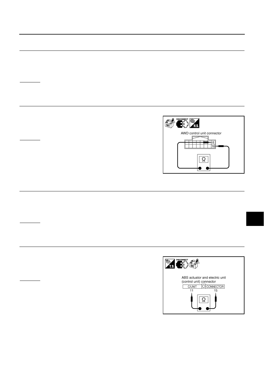
2.
CHECK HARNESS FOR OPEN CIRCUIT
1.
Disconnect ABS actuator and electric unit (control unit) connector.
2.
Check resistance between ABS actuator and electric unit (con-
trol unit) harness connector E24 terminals 11 (L) and 15 (Y).
OK or NG
OK
>> Replace ABS actuator and electric unit (control unit).
NG
>> Repair harness between ABS actuator and electric unit
(control unit) and IPDM E/R.
8 (L) - 16 (Y)
: Approx. 54 - 66
Ω
SKIA6889E
11 (L) - 15 (Y)
: Approx. 54 - 66
Ω
SKIA5019E