Nissan Murano Z50 (2004 year). Manual - part 165
CAN SYSTEM (TYPE 13)
LAN-457
[CAN]
C
D
E
F
G
H
I
J
L
M
A
B
LAN
Revision: 2004 November
2004 Murano
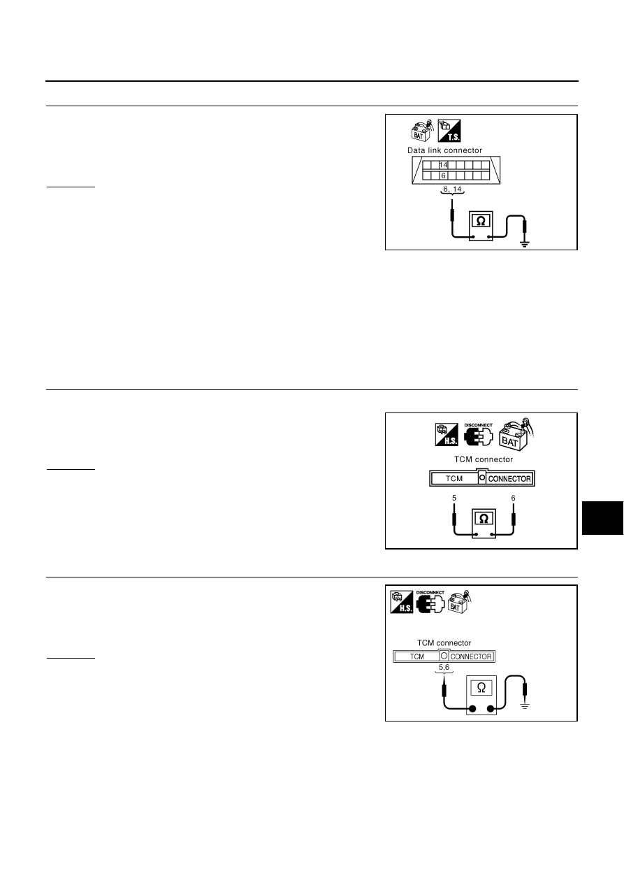
3.
CHECK HARNESS FOR SHORT CIRCUIT
Check continuity between data link connector M24 terminals 6 (L),
14 (Y) and ground.
OK or NG
OK
>> GO TO 4.
NG
>> Check the following harnesses. If any harness is dam-
aged, repair the harness.
●
Harness between data link connector and ECM
●
Harness between data link connector and low tire
pressure warning control unit
●
Harness between data link connector and harness connector M82
●
Harness between data link connector and display unit
●
Harness between data link connector and BCM
●
Harness between data link connector and unified meter and A/C amp.
●
Harness between data link connector and steering angle sensor
●
Harness between data link connector and harness connector M9
4.
CHECK HARNESS FOR SHORT CIRCUIT
1.
Disconnect TCM connector.
2.
Check continuity between TCM harness connector F103 termi-
nals 5 (L) and 6 (Y).
OK or NG
OK
>> GO TO 5.
NG
>> Repair harness between TCM and harness connector
F102.
5.
CHECK HARNESS FOR SHORT CIRCUIT
Check continuity between TCM harness connector F103 terminals 5
(L), 6 (Y) and ground.
OK or NG
OK
>> GO TO 6.
NG
>> Repair harness between TCM and harness connector
F102.
6 (L) - Ground
: Continuity should not exist.
14 (Y) - Ground
: Continuity should not exist.
SKIA6874E
5 (L) - 6 (Y)
: Continuity should not exist.
PKIA0817E
5 (L) - Ground
: Continuity should not exist.
6 (Y) - Ground
: Continuity should not exist.
SKIA5020E