Nissan Murano Z50 (2004 year). Manual - part 101
DTC P1446 EVAP CANISTER VENT CONTROL VALVE
EC-527
C
D
E
F
G
H
I
J
K
L
M
A
EC
Revision: 2004 November
2004 Murano
Specification data are reference values and are measured between each terminal and ground.
CAUTION:
Do not use ECM ground terminals when measuring input/output voltage. Doing so may result in dam-
age to the ECM's transistor. Use a ground other than ECM terminals, such as the ground.
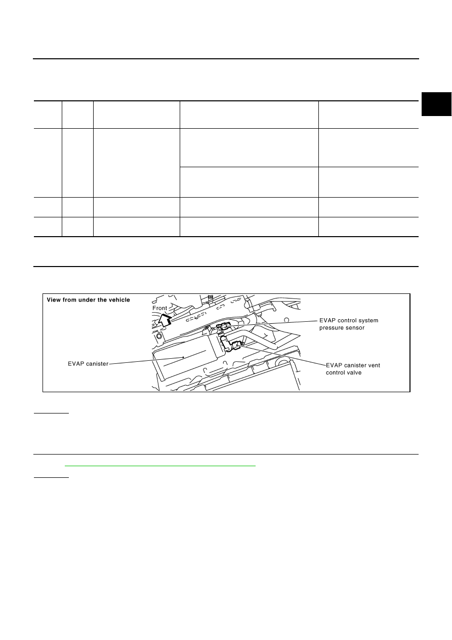
Diagnostic Procedure
ABS004M2
1.
CHECK RUBBER TUBE
1.
Turn ignition switch OFF.
2.
Disconnect rubber tube connected to EVAP canister vent control valve.
3.
Check the rubber tube for clogging.
OK or NG
OK
>> GO TO 2.
NG
>> Clean rubber tube using an air blower.
2.
CHECK EVAP CANISTER VENT CONTROL VALVE
Refer to
EC-529, "EVAP CANISTER VENT CONTROL VALVE"
OK or NG
OK
>> GO TO 3.
NG
>> Replace EVAP canister vent control valve.
TER-
MINAL
NO.
WIRE
COLOR
ITEM
CONDITION
DATA (DC Voltage)
111
W/B
ECM relay
(Self shut-off)
[Engine is running]
[Ignition switch: OFF]
●
For a few seconds after turning ignition
switch OFF
0 - 1.5V
[Ignition switch: OFF]
●
A few seconds passed after turning ignition
switch OFF
BATTERY VOLTAGE
(11 - 14V)
117
R
EVAP canister vent control
valve
[Ignition switch: ON]
BATTERY VOLTAGE
(11 - 14V)
119
120
R/B
R/B
Power supply for ECM
[Ignition switch: ON]
BATTERY VOLTAGE
(11 - 14V)
PBIB1365E