Nissan Murano Z50 (2004 year). Manual - part 16


  Index      Manuals     Nissan Murano Z50 (2004 year) - Service and Repair Manual


Search            copyright infringement  


Content      ..     14      15      16      17     ..


Nissan Murano Z50 (2004 year). Manual - part 16


AUDIO

AV-67

C

D

E

F

G

H

I

J

L

M

A

B

AV

Revision: 2004 November

2004 Murano

7.

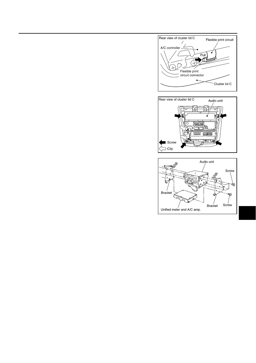
Unlock FPC (Flexible Print Circuit) connector lock on A/C and
AV switch side.

8.

Pull off flexible printed circuit from connector.

CAUTION:

Make sure mating surface of FPC (Flexible Print Circuit) and
the direction of connector terminal.

9.

Remove screws (4) and clips (2). Then remove audio unit from
cluster lid C.

10. Remove audio unit screws (8), unified meter and A/C amp.

screws (2) and remove bracket.

CAUTION:

When carrying audio unit body, do not touch internal
mechanism access from cassette tape slot.

Be careful not to allow foreign material to enter from cas-
sette tape slot.

Use appropriate screws for each, as screws for audio unit
are different from that for unified meter and A/C amp.

INSTALLATION

Installation is the reverse order of removal. 

PKIA2444E

PKIA2448E

PKIA2449E

AV-68

AUDIO

Revision: 2004 November

2004 Murano

Removal and Installation for A/C and AV Switch

AKS004NU

REMOVAL

1.

Remove audio unit from cluster lid C. Refer to 

AV-66, "Removal and Installation of Audio Unit"

 .

2.

Remove screws (8) and remove A/C and AV switch.

INSTALLATION

Installation is the reverse order of removal.

PKIA2452E

1.

Front finisher

2.

A/C and AV switch

3.

Screws

4.

Screws

5.

Cluster lid C

PKIA2451E

AUDIO

AV-69

C

D

E

F

G

H

I

J

L

M

A

B

AV

Revision: 2004 November

2004 Murano

Removal and Installation of Audio Steering Wheel Switch

AKS00AS9

REMOVAL

1.

Remove steering wheel. Refer to 

PS-9, "Removal and Installation"

 .

2.

Remove steering wheel cover.

3.

Remove screws (2) and remove audio steering wheel switch.

INSTALLATION

Installation is the reverse order of removal.

Removal and Installation of Front Door Speaker (Base system)

AKS004NV

REMOVAL

1.

Remove door finisher. Refer to 

EI-30, "DOOR FINISHER"

 .

2.

Remove screws (4) and remove speaker.

3.

Remove screws (4) and remove bracket.

INSTALLATION

Installation is the reverse order of removal.

Removal and Installation of Front Door Speaker (BOSE system)

AKS004NW

REMOVAL

1.

Remove door finisher. Refer to 

EI-30, "DOOR FINISHER"

 .

2.

Remove screws (3) and remove speaker.

3.

Remove screws (3) and remove bracket.

INSTALLATION

Installation is the reverse order of removal.

SKIB0039E

PKIA2454E

PKIA2455E

AV-70

AUDIO

Revision: 2004 November

2004 Murano

Removal and Installation of Rear Door Speaker (Base system)

AKS004NX

REMOVAL

1.

Remove door finisher. Refer to 

EI-30, "DOOR FINISHER"

 .

2.

Remove screws (3) and remove speaker.

INSTALLATION

Installation is the reverse order of removal.

Removal and Installation of Rear Door Speaker (BOSE system)

AKS004NY

REMOVAL

1.

Remove door finisher. Refer to 

EI-30, "DOOR FINISHER"

 .

2.

Remove screws (3) and remove speaker.

INSTALLATION

Installation is the reverse order of removal.

Removal and Installation of Tweeter

AKS004NZ

REMOVAL

1.

Remove side ventilator assembly. Refer to 

IP-10, "INSTRUMENT PANEL ASSEMBLY"

 .

2.

Remove instrument side finisher. Refer to 

IP-10, "INSTRUMENT PANEL ASSEMBLY"

 .

3.

Remove screws (2) and remove tweeter.

INSTALLATION

Installation is the reverse order of removal.

PKIA2456E

PKIA2457E

PKIA2458E

AUDIO

AV-71

C

D

E

F

G

H

I

J

L

M

A

B

AV

Revision: 2004 November

2004 Murano

Removal and Installation of Woofer

AKS004O0

REMOVAL

1.

Open luggage floor finisher (center). Refer to 

EI-38, "LUGGAGE FLOOR TRIM"

 .

2.

Remove woofer clamp and remove connector.

3.

Remove woofer.

CAUTION:

Connectors must be placed in the left side, when installed.

INSTALLATION

Installation is the reverse order of removal.

Removal and Installation of BOSE Speaker Amp.

AKS004R3

REMOVAL

1.

Remove luggage floor finisher (front). Refer to 

EI-38, "LUGGAGE FLOOR TRIM"

 .

2.

Remove screws (4) and connectors (2) and remove BOSE
speaker amp. from luggage floor.

3.

Remove screws (4) and remove bracket.

INSTALLATION

Installation is the reverse order of removal.

PKIA2459E

PKIA2460E

PKIA2461E

AV-72

AUDIO ANTENNA

Revision: 2004 November

2004 Murano

AUDIO ANTENNA

PFP:28200

Location of Antenna

AKS004O1

Removal and Installation of Roof Antenna

AKS004O3

REMOVAL

1.

Remove head lining. Refer to 

EI-36, "HEADLINING"

 .

2.

Remove nut and antenna base.

3.

Remove instrument panel. Refer to 

IP-10, "INSTRUMENT PANEL ASSEMBLY"

 .

4.

Remove antenna feeder (upper) and antenna feeder (lower).

5.

Remove clips (5), and separate antenna feeder (upper) from vehicle.

INSTALLATION

Installation is the reverse order of removal.

PKIA2462E

PKIA2463E

INTEGRATED DISPLAY SYSTEM

AV-73

C

D

E

F

G

H

I

J

L

M

A

B

AV

Revision: 2004 November

2004 Murano

INTEGRATED DISPLAY SYSTEM

PFP:28090

System Description

AKS004XS

A/C AND AV SWITCH SYSTEM

Refer to Owner

s Manual for A/C and AV switch operating instructions.

Using the A/C and AV switch at the center of the instrument panel, the controls of the following systems are
centralized:

Integrated display system (Drive computer, setting screen, clock, etc.)

Auto A/C system

Audio system

PRECAUTION OF LCD MONITOR

In order to use LED for backlight of a display, by in car temperature, brightness may change. In low tem-
perature, the refreshing rate of the picture also becomes low because of the low response of the LCD
monitor. When passenger room becomes warm, however, the LCD recovers the normal display.

Backlight sometimes flickers or darkens according to the total consumption hours and the number of times
switched ON and OFF. In this case, display unit should be replaced.(Exchange only of backlight is impos-
sible.)

POWER SUPPLY AND GROUND
Power Is Supplied At All Times

through 15A fuse [No. 38, located in fuse and fusible link block]

to audio unit terminal 6

to display unit terminal 1

to A/C and AV switch terminal 1.

When Ignition Switch Is In ACC or ON Position, Power Is Supplied

through 10A fuse [No. 6, located in fuse block (J/B)]

to unified meter and A/C amp. terminal 35

to display unit terminal 2

to audio unit terminal 10

to A/C and AV switch terminal 2

to BCM terminal 11.

When Ignition Switch Is In ON or START Position, Power Is Supplied

through 10A fuse [No. 12, located in fuse block (J/B)]

to unified meter and A/C amp. terminal 22

to display unit terminal 3.

Ground Is Supplied

to unified meter and A/C amp. terminals 29, 30

to display unit terminal 6

to A/C and AV switch terminal 5

to BCM terminals 49, 52

to low tire pressure warning control unit terminal 20

through body grounds M14 and M78.

AV-74

INTEGRATED DISPLAY SYSTEM

Revision: 2004 November

2004 Murano

DRIVE COMPUTER

Refer to Owner

s Manual for drive computer operating instructions.

TRIP Switch

When “TRIP” switch is pushed, display TRIP screen. As TRIP infor-
mation, it indicates journey time (TIME), trip odometer (DIST), and
average vehicle speed (AVG).
Pushing “TRIP” switch once cycles display from TRIP 1

TRIP

2

Display OFF

TRIP 1.

“TIME”

Journey time indication is conducted by reset or battery connec-
tion.

When pushing “TRIP RESET” or “TRIP” switch more than
approximately 1.5 seconds, journey time will be reset.

If journey time is reset, journey distance and average speed will
be reset at the same time.

“DIST”

Trip odometer indication is conducted by vehicle speed signal.

When pushing “TRIP RESET” or “TRIP” switch more than approximately 1.5 seconds, driving distance will
be reset.

If trip odometer is reset, journey time average speed will be reset at the same time.

“AVG”

Average speed indication is conducted by running distance and running time.

Indication will be renewed every 30 seconds.

When pushing “TRIP RESET” or “TRIP” switch more than approximately 1.5 seconds, average speed will
be reset.

After reset operation, the displays shows “ ” for 30 seconds.

FUEL ECON Switch

When “FUEL ECON” switch is pushed, display FUEL ECON screen.
As FUEL ECON information, it indicates average fuel consumption
(AVG), and distance to empty (DTE).
Pushing “FUEL ECON” switch once cycles display from FUEL
ECON

Display OFF

FUEL ECON.

“AVG” (Average Fuel Consumption)

Average fuel consumption indication is conducted by ECM pulse
signal and vehicle speed signal after system is reset.

Indication will be renewed every 30 seconds.

When pushing “TRIP RESET” or “FUEL ECON” switch more
than approximately 1.5 seconds, average fuel economy will be
reset.

After reset operation, the display shows “ . ” until the vehicle is driven 1,600 ft. (500 m) or 30 seconds
has passed.

“DTE” (Distance to Empty)

Distance to empty receives via CAN communication and indicates values calculated by meter.

Display range is max 999 miles (max 999 km).

If low-fuel WARNING is received from combination meter via CAN communication, distance to empty indi-
cation will be “ ”.

Indication will be renewed every 30 seconds.

SKIA5916E

SKIA5917E

INTEGRATED DISPLAY SYSTEM

AV-75

C

D

E

F

G

H

I

J

L

M

A

B

AV

Revision: 2004 November

2004 Murano

MAINT Switch (Maintenance Switch)

When “MAINT” switch is pushed, display vehicle information screen. As vehicle information, it indicates
engine oil, tire rotation, and tire pressure.

Pushing “MAINT” switch once cycles display from engine oil

tire rotation

tire pressure

Note


engine oil.

NOTE:
There is not low tire pressure warning system becomes display OFF. 

Engine Oil and Tire Rotation

Operating the joystick left/right, replace distance can be set.

When journey distance is the same as replace distance, alert is
displayed. (SERVICE ALERT setting is ON.)

Selected replace distance is 0 - 7,500 miles (0 - 12,000 km) in
increments of 500 mile (800 km).

Push and hold “TRIP RESET” or “MAINT” switch for 1.5 sec-
onds or longer, reset present journey distance.

During driving, cannot change settings.

Tire Pressure

Tire pressure signal is received from low tire pressure warning
control unit via CAN communication. 

Tire pressure is displayed.

When FLAT TIRE signal is received from low tire pressure warn-
ing control unit, “FLAT TIRE” is displayed.

H,M Switch

When “H” or “M” switch is pushed and held for 1.5 seconds or more, mode is changed to clock mode.

Then “hour” and “minute” are flashed.

When “H” switch is pushed, “hour” is adjusted.

When “M” switch is pushed, “minute” is adjusted.

SKIA5918E

SKIA5919E

AV-76

INTEGRATED DISPLAY SYSTEM

Revision: 2004 November

2004 Murano

SETTING SCREEN

When the “SETTING” button is pushed, the following menu will display on the screen.
DISPLAY ON/OFF 

 LANGUAGE 

 BEEP SET 

 SERVICE ALERT 

 PERSONALIZED SETTING MENU

 OFF

Adjustable Vehicle Status

*: If equipped

Setting items

Operation

DISPLAY

To turn off the display, choose “OFF” on the screen using the joystick.

The confirmation will appear. Select “YES” to turn off, and “NO” to 
cancel.

To turn on the display, push display screen control, air conditioner or 
audio button.

LANGUAGE

To change the language, choose English or French using the joystick.

BEEP SET

To turn on/off the button beep sound, choose “ON” or “OFF” using the 
joystick.

SERVICE ALERT

To display the maintenance information on the screen when it has 
reached to the preset distance, choose “ON”.

PERSONALIZED 
SETTING MENU

SLIDE BACK DR SEAT ON EXIT*

To set the driver's seat so that it automatically moves back and returns 
to the original position for ease of entry and exit, choose “ON”.

REMOTE UNLOCK DOOR LOGIC*

To set the unlock doors of the 1st unlocking operation, choose the 
desired function.
Only the driver side door 

 All the doors

HORN CHIRP WITH REMOTE*

To set the horn chirp mode that occurs when pushing the LOCK button 
on the remote controller, choose the desired function.

LIGHTS FLASH WITH REMOTE*

To set the hazard indicator flash mode when the “LOCK” or “UNLOCK” 
button on the remote controller is pushed, choose the desired function.

AUTO RE-LOCK TIME*

To set the auto door re-lock time, choose the desired time.

AUTO HEADLIGHTS SENSITIVITY*

To set the sensitivity level of the automatic headlights, choose the level.

AUTO HEADLIGHTS OFF DELAY*

To set the time for how long it takes the automatic turn off timer to extin-
guish the headlights in the AUTO position, select the “Automatic Head-
lights Off Delay” key, then move the joystick to the left or right to adjust 
the timer.

SPEED SENSING WIPER INTERVAL*

To turn on the speed sensing wiper, choose “ON”.

CONFIRM RESET SETTINGS*

To reset all settings of the personalized settings to the initial conditions, 
choose “YES”.

RESET ALL SETTINGS*

To reset all settings of the personalized settings to the initial conditions, 
push “ENTER”.

INTEGRATED DISPLAY SYSTEM

AV-77

C

D

E

F

G

H

I

J

L

M

A

B

AV

Revision: 2004 November

2004 Murano

D/N Screen

When D/N switch is pushed, change screen of adjustment lumi-
nance.

If push D/N again when display adjustment luminance, change
DAY-NIGHT(NIGHT-DAY) mode (screen of adjustment lumi-
nance).
As follows:

Push “PREV” or not operate for 10sec. when displayed screen
of adjustment luminance, back to default screen (same mode).

Can adjust luminance by joystick (R/L) in adjustment screen.

Adjustment range is a 12 stage (MIN to MAX) and default set value is 10 (DAY) and 4 (NIGHT).

WARNING INDICATIONS

The door open warning will appear when the door is not securely closed while driving over 3 MPH (5 km/
h).

The door open warning will disappear when the vehicle speed slows down under 5 km/h (3 MPH) even if
the door is not securely closed yet.

AV COMMUNICATION LINE

Display unit is controlled by the following unit with AV communication line.

A/C and AV switch

CAN Communication System Description

AKS007PU

CAN (Controller Area Network) is a serial communication line for real time application. It is an on-vehicle mul-
tiplex communication line with high data communication speed and excellent error detection ability. Modern
vehicles are equipped with many electronic control units and each control unit shares information and links
with other control units during operation (not independent). In CAN communication, control units are con-
nected with 2 communication lines (CAN H line, CAN L line) allowing a high rate of information transmission
with less wiring. Each control unit transmits/receives data but selectively reads required data only.

CAN Communication Unit 

AKS007PV

Refer to 

LAN-8, "CAN Communication Unit"

 . 

Component Parts and Harness Connector Location 

AKS004XU

Now

Change display

DAY

DAY (adjustment)

NIGHT (adjustment)

DAY (adjustment)

·····

NIGHT

NIGHT (adjustment)

DAY (adjustment)

NIGHT (adjustment)

·····

SKIA4374E

SKIA9937E

AV-78

INTEGRATED DISPLAY SYSTEM

Revision: 2004 November

2004 Murano

Schematic

AKS004YZ

TKWA1728E

INTEGRATED DISPLAY SYSTEM

AV-79

C

D

E

F

G

H

I

J

L

M

A

B

AV

Revision: 2004 November

2004 Murano

Wiring Diagram — INF/D — 

AKS004Z0

TKWA0838E

AV-80

INTEGRATED DISPLAY SYSTEM

Revision: 2004 November

2004 Murano

TKWA0839E

INTEGRATED DISPLAY SYSTEM

AV-81

C

D

E

F

G

H

I

J

L

M

A

B

AV

Revision: 2004 November

2004 Murano

TKWA1056E

AV-82

INTEGRATED DISPLAY SYSTEM

Revision: 2004 November

2004 Murano

TKWA1729E


Content      ..     14      15      16      17     ..