Nissan Murano Z50 (2003 year). Manual - part 214
LAN-1038
[CAN]
CAN SYSTEM (TYPE 30)
Revision; 2004 April
2003 Murano
3.
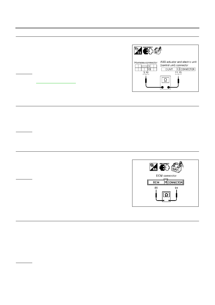
CHECK HARNESS FOR OPEN CIRCUIT
1.
Disconnect ABS actuator and electric unit (control unit) connector.
2.
Check continuity between harness connector E105 terminals 3
(L), 10 (Y) and ABS actuator and electric unit (control unit) har-
ness connector E24 terminals 11 (L), 15 (Y).
OK or NG
OK
>> Connect all the connectors and diagnose again. Refer to
.
NG
>> Repair harness.
ECM Circuit Check
AKS0077G
1.
CHECK CONNECTOR
1.
Turn ignition switch OFF.
2.
Disconnect the negative battery terminal.
3.
Check terminals and connector of ECM for damage, bend and loose connection (control module side and
harness side).
OK or NG
OK
>> GO TO 2.
NG
>> Repair terminal or connector.
2.
CHECK HARNESS FOR OPEN CIRCUIT
1.
Disconnect ECM connector.
2.
Check resistance between ECM harness connector M80 termi-
nals 94 (L) and 86 (Y).
OK or NG
OK
>> Replace ECM.
NG
>> Repair harness between ECM and TCM.
TCM Circuit Check
AKS0077H
1.
CHECK CONNECTOR
1.
Turn ignition switch OFF.
2.
Disconnect the negative battery terminal.
3.
Check following terminals and connectors for damage, bend and loose connection (control module side
and harness side).
●
TCM connector
●
Harness connector F102
●
Harness connector M82
OK or NG
OK
>> GO TO 2.
NG
>> Repair terminal or connector.
3 (L) - 11 (L)
: Continuity should exist.
10 (Y) - 15 (Y)
: Continuity should exist.
SKIA5017E
94 (L) - 86 (Y)
: Approx. 108 - 132
Ω
PKIA0816E