Nissan Murano Z50 (2003 year). Manual - part 23
NAVIGATION SYSTEM
AV-161
C
D
E
F
G
H
I
J
L
M
A
B
AV
Revision; 2004 April
2003 Murano
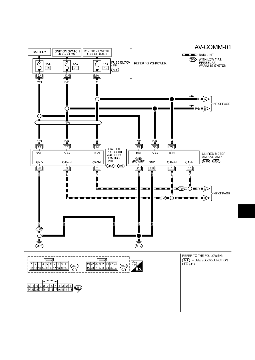
Wiring Diagram — COMM —
AKS004RB
TKWA0843E
|
|
|
NAVIGATION SYSTEM AV-161 C D E F G H I J L M A B AV Revision; 2004 April 2003 Murano Wiring Diagram — COMM — AKS004RB TKWA0843E |