Nissan Murano Z51 (2008 year). Manual - part 299
PWO-2
< COMPONENT DIAGNOSIS >
CIGARETTE LIGHTER
COMPONENT DIAGNOSIS
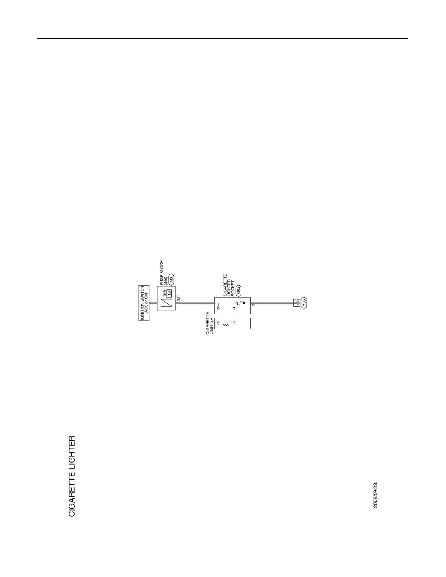
CIGARETTE LIGHTER
Wiring Diagram - CIGARETTE LIGHTER -
INFOID:0000000003372920
JCMWM3147GB
Revision: 2008 October
2009 Murano
|
|
|
PWO-2 < COMPONENT DIAGNOSIS > CIGARETTE LIGHTER COMPONENT DIAGNOSIS CIGARETTE LIGHTER Wiring Diagram - CIGARETTE LIGHTER - INFOID:0000000003372920 JCMWM3147GB Revision: 2008 October 2009 Murano |