Nissan Murano Z51 (2008 year). Manual - part 277
PCS
RELAY CONTROL SYSTEM
PCS-3
< FUNCTION DIAGNOSIS >
[IPDM E/R]
C
D
E
F
G
H
I
J
K
L
B
A
O
P
N
FUNCTION DIAGNOSIS
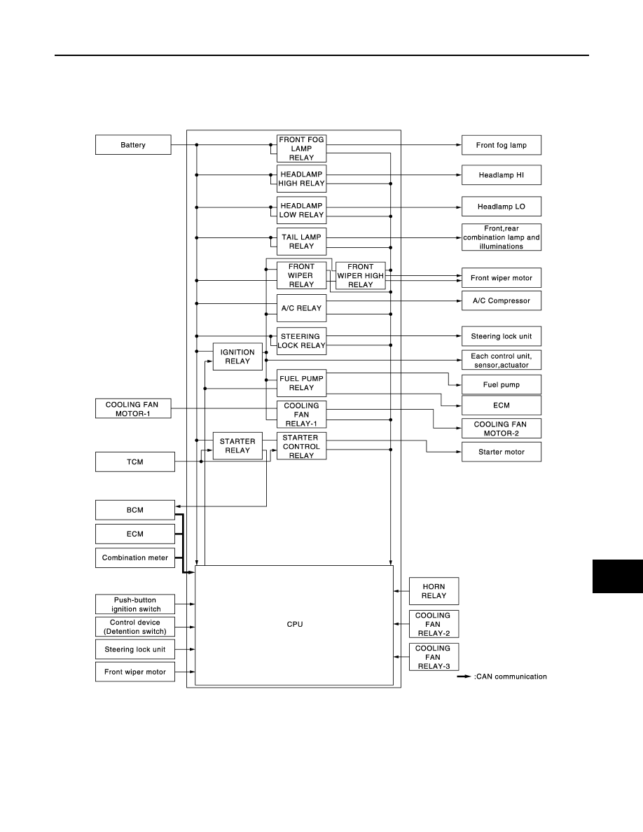
RELAY CONTROL SYSTEM
System Diagram
INFOID:0000000003420420
System Description
INFOID:0000000003420421
IPDM E/R activates the internal control circuit to perform the relay ON-OFF control according to the input sig-
nals from various sensors and the request signals received from control units via CAN communication.
CAUTION:
IPDM E/R integrated relays cannot be removed.
JPMIA0861GB
Revision: 2008 October
2009 Murano