Nissan Murano Z51 (2008 year). Manual - part 179
CYLINDER BLOCK
EM-129
< DISASSEMBLY AND ASSEMBLY >
C
D
E
F
G
H
I
J
K
L
M
A
EM
N
P
O
• Measure the inner diameter of connecting rod big end with an
inside micrometer.
• If out of the standard, replace connecting rod assembly.
CONNECTING ROD BUSHING OIL CLEARANCE
Connecting Rod Bushing Inner Diameter
Measure the inner diameter of connecting rod bushing with an inside
micrometer (A).
Piston Pin Outer Diameter
Measure the outer diameter of piston pin with a micrometer (A).
Connecting Rod Bushing Oil Clearance
(Connecting rod bushing oil clearance) = (Connecting rod bushing inner diameter) – (Piston pin outer diame-
ter)
• If the calculated value exceeds the limit, replace connecting rod assembly and/or piston and piston pin
assembly.
• If replacing piston and piston pin assembly, refer to
• If replacing connecting rod assembly, refer to
to select the connecting rod bearing.
1
: Connecting rod
Standard
: Refer to
JPBIA0222ZZ
Standard
: Refer to
JPBIA0223ZZ
Standard
: Refer to
JPBIA0218ZZ
Standard and limit
: Refer to
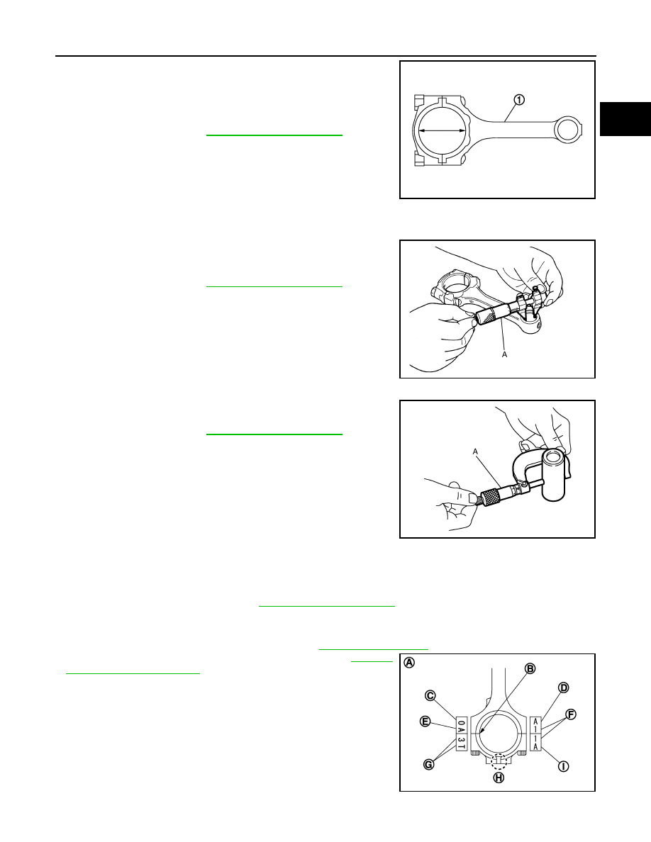
A
: Sample codes
B
: Bearing stopper groove
C
: Small-end diameter grade
D
: Standard stamp
E
: Weight grade
F
: Cylinder No.
G
: Management code
JPBIA0208ZZ
Revision: 2008 October
2009 Murano