Nissan Murano Z51 (2008 year). Manual - part 159
EC-360
< COMPONENT DIAGNOSIS >
[VQ35DE]
P1225 TP SENSOR
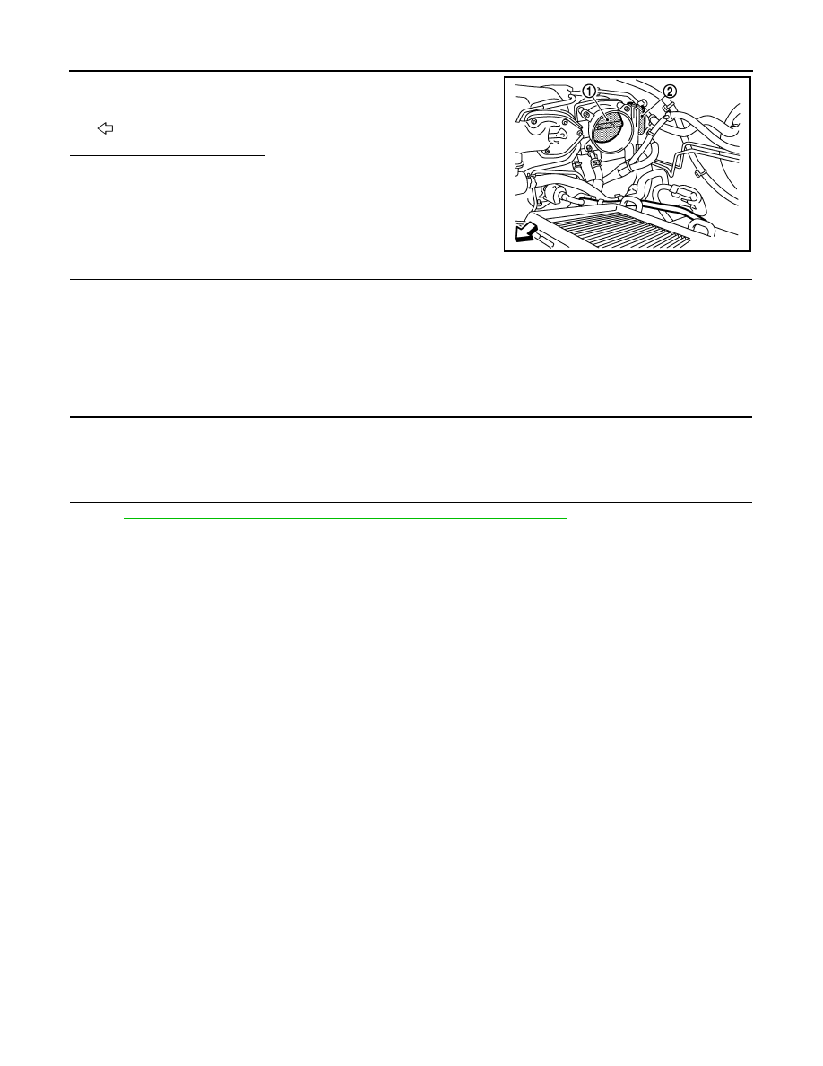
3.
Check if foreign matter is caught between the throttle valve (1)
and the housing.
-
Electric throttle control actuator (2)
-
: Vehicle front
Is the inspection result normal?
YES
>> GO TO 2.
NO
>> Remove the foreign matter and clean the electric throttle
control actuator inside.
2.
REPLACE ELECTRIC THROTTLE CONTROL ACTUATOR
1.
Replace electric throttle control actuator.
2.
Go to
EC-360, "Special Repair Requirement"
.
>> INSPECTION END
Special Repair Requirement
INFOID:0000000003591588
1.
PERFORM THROTTLE VALVE CLOSED POSITION LEARNING
EC-17, "THROTTLE VALVE CLOSED POSITION LEARNING : Special Repair Requirement"
>> GO TO 2.
2.
PERFORM IDLE AIR VOLUME LEARNING
EC-17, "IDLE AIR VOLUME LEARNING : Special Repair Requirement"
>> END
JMBIA1132ZZ
Revision: 2008 October
2009 Murano