Nissan Murano Z51 (2008 year). Manual - part 53
AV
POWER SUPPLY AND GROUND CIRCUIT
AV-621
< COMPONENT DIAGNOSIS >
[BOSE AUDIO WITH NAVIGATION]
C
D
E
F
G
H
I
J
K
L
M
B
A
O
P
Is the inspection result normal?
YES
>> INSPECTION END
NO
>> Repair harness or connector.
CAMERA CONTROL UNIT
CAMERA CONTROL UNIT : Diagnosis Procedure
INFOID:0000000003356629
1.
CHECK FUSE
Check for blown fuses.
Is the inspection result normal?
YES
>> GO TO 2.
NO
>> Be sure to eliminate the cause of malfunction before installing new fuse.
2.
CHECK POWER SUPPLY CIRCUIT
Check voltage between camera control unit harness connector and ground.
Is the inspection result normal?
YES
>> GO TO 3.
NO
>> Check harness between camera control unit and fuse.
3.
CHECK GROUND CIRCUIT
1.
Turn ignition switch OFF.
2.
Disconnect camera control unit connector.
3.
Check continuity between camera control unit harness connector and ground.
Is the inspection result normal?
YES
>> INSPECTION END
NO
>> Repair harness or connector.
BOSE AMP.
BOSE AMP. : Diagnosis Procedure
INFOID:0000000003356630
1.
CHECK FUSE
Check for blown fuses.
Is the inspection result normal?
YES
>> GO TO 2.
NO
>> Be sure to eliminate the cause of malfunction before installing new fuse.
2.
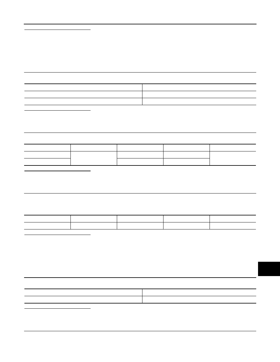
CHECK POWER SUPPLY CIRCUIT
Check voltage between BOSE amp. harness connector and ground.
Power source
Fuse No.
Battery
35
Ignition switch ACC or ON
19
Signal name
Connector No.
Terminal No.
Ignition switch position
Value (Approx.)
Battery power supply
B60
32
OFF
Battery voltage
ACC power supply
30
ACC
Signal name
Connector No.
Terminal No.
Ignition switch position
Continuity
Ground
B60
31
OFF
Existed
Power source
Fuse No.
Battery
23, 24
Revision: 2008 October
2009 Murano