Nissan Murano. Manual - part 955


  Главная      Nissan     Nissan Murano (2014 year) - Service Manual


поиск по сайту            


содержание   ..  953  954  955  956   ..


Nissan Murano. Manual - part 955


LAN

MAIN LINE BETWEEN DLC AND TCM CIRCUIT

LAN-131

< DTC/CIRCUIT DIAGNOSIS >

[CAN SYSTEM (TYPE 5)]

C

D

E

F

G

H

I

J

K

L

B

A

O

P

N

MAIN LINE BETWEEN DLC AND TCM CIRCUIT

Diagnosis Procedure

INFOID:0000000010092824

1.

CHECK CONNECTOR

1.

Turn the ignition switch OFF.

2.

Disconnect the battery cable from the negative terminal.

3.

Check the following terminals and connectors for damage, bend and loose connection (connector side
and harness side).

-

Harness connector M11

-

Harness connector E105

Is the inspection result normal?

YES

>> GO TO 2.

NO

>> Repair the terminal and connector.

2.

CHECK HARNESS CONTINUITY (OPEN CIRCUIT)

1.

Disconnect the harness connectors M11 and E105.

2.

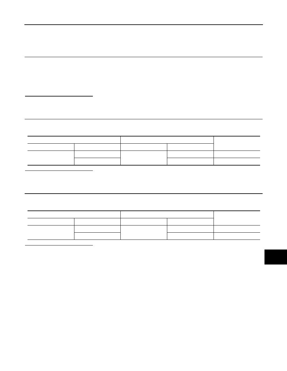
Check the continuity between the data link connector and the harness connector.

Is the inspection result normal?

YES

>> GO TO 3.

NO

>> Repair the main line between the data link connector and the harness connector M11.

3.

CHECK HARNESS CONTINUITY (OPEN CIRCUIT)

1.

Disconnect the harness connectors E6 and F123.

2.

Check the continuity between the harness connectors.

Is the inspection result normal?

YES (Present error)>>Check CAN system type decision again.
YES (Past error)>>Error was detected in the main line between the data link connector and the TCM. 
NO

>> Repair the main line between the harness connectors E105 and E6.

Data link connector

Harness connector

Continuity

Connector No.

Terminal No.

Connector No.

Terminal No.

M4

6

M11

12

Existed

14

11

Existed

Harness connector

Harness connector

Continuity

Connector No.

Terminal No.

Connector No.

Terminal No.

E105

12

E6

1

Existed

11

8

Existed

LAN-132

< DTC/CIRCUIT DIAGNOSIS >

[CAN SYSTEM (TYPE 5)]

ECM BRANCH LINE CIRCUIT

ECM BRANCH LINE CIRCUIT

Diagnosis Procedure

INFOID:0000000010092825

1.

CHECK CONNECTOR

1.

Turn the ignition switch OFF.

2.

Disconnect the battery cable from the negative terminal.

3.

Check the following terminals and connectors for damage, bend and loose connection (unit side and con-
nector side).

-

Models with automatic back door system

ECM

Harness connector E104

Harness connector B4

-

Models without automatic back door system

ECM

Harness connector E105

Harness connector M11

Is the inspection result normal?

YES

>> GO TO 2.

NO

>> Repair the terminal and connector.

2.

CHECK HARNESS FOR OPEN CIRCUIT

1.

Disconnect the connector of ECM.

2.

Check the resistance between the ECM harness connector terminals.

Is the measurement value within the specification?

YES

>> GO TO 3.

NO

>> Repair the ECM branch line.

3.

CHECK POWER SUPPLY AND GROUND CIRCUIT

Check the power supply and the ground circuit of the ECM. Refer to 

EC-148, "Diagnosis Procedure"

.

Is the inspection result normal?

YES (Present error)>>Replace the ECM. Refer to 

EC-16, "ADDITIONAL SERVICE WHEN REPLACING

CONTROL UNIT : Special Repair Requirement"

.

YES (Past error)>>Error was detected in the ECM branch line.
NO

>> Repair the power supply and the ground circuit.

ECM harness connector

Resistance (

)

Connector No.

Terminal No.

E16

98

97

Approx. 108 – 132

LAN

PWBD BRANCH LINE CIRCUIT

LAN-133

< DTC/CIRCUIT DIAGNOSIS >

[CAN SYSTEM (TYPE 5)]

C

D

E

F

G

H

I

J

K

L

B

A

O

P

N

PWBD BRANCH LINE CIRCUIT

Diagnosis Procedure

INFOID:0000000010092826

1.

CHECK CONNECTOR

1.

Turn the ignition switch OFF.

2.

Disconnect the battery cable from the negative terminal.

3.

Check the terminals and connectors of the automatic back door control unit for damage, bend and loose
connection (unit side and connector side).

Is the inspection result normal?

YES

>> GO TO 2.

NO

>> Repair the terminal and connector.

2.

CHECK HARNESS FOR OPEN CIRCUIT

1.

Disconnect the connector of automatic back door control unit.

2.

Check the resistance between the automatic back door control unit harness connector terminals.

Is the measurement value within the specification?

YES

>> GO TO 3.

NO

>> Repair the automatic back door control unit branch line.

3.

CHECK POWER SUPPLY AND GROUND CIRCUIT

Check the power supply and the ground circuit of the automatic back door control unit. Refer to 

DLK-95,

"AUTOMATIC BACK DOOR CONTROL UNIT : Diagnosis Procedure"

Is the inspection result normal?

YES (Present error)>>Replace the automatic back door control unit. Refer to 

DLK-368, "Removal and Instal-

lation"

.

YES (Past error)>>Error was detected in the automatic back door control unit branch line.
NO

>> Repair the power supply and the ground circuit.

Automatic back door control unit harness connector

Resistance (

)

Connector No.

Terminal No.

B8

6

7

Approx. 54 – 66

LAN-134

< DTC/CIRCUIT DIAGNOSIS >

[CAN SYSTEM (TYPE 5)]

AV BRANCH LINE CIRCUIT

AV BRANCH LINE CIRCUIT

Diagnosis Procedure

INFOID:0000000010092827

1.

CHECK CONNECTOR

1.

Turn the ignition switch OFF.

2.

Disconnect the battery cable from the negative terminal.

3.

Check the terminals and connectors of the AV control unit for damage, bend and loose connection (unit
side and connector side).

Is the inspection result normal?

YES

>> GO TO 2.

NO

>> Repair the terminal and connector.

2.

CHECK HARNESS FOR OPEN CIRCUIT

1.

Disconnect the connector of AV control unit.

2.

Check the resistance between the AV control unit harness connector terminals.

-

Models with navigation system

-

Models without navigation system

Is the measurement value within the specification?

YES

>> GO TO 3.

NO

>> Repair the AV control unit branch line.

3.

CHECK POWER SUPPLY AND GROUND CIRCUIT

Check the power supply and the ground circuit of the AV control unit. Refer to the following.
• Base audio with color display: 

AV-118, "AV CONTROL UNIT : Diagnosis Procedure"

• BOSE audio without navigation: 

AV-244, "AV CONTROL UNIT : Diagnosis Procedure"

• BOSE audio with navigation: 

AV-419, "AV CONTROL UNIT : Diagnosis Procedure"

Is the inspection result normal?

YES (Present error)>>Replace the AV control unit. Refer to the following.

• Base audio with color display: 

AV-149, "Removal and Installation"

• BOSE audio without navigation: 

AV-276, "Removal and Installation"

• BOSE audio with navigation: 

AV-448, "Removal and Installation"

YES (Past error)>>Error was detected in the AV control unit branch line.
NO

>> Repair the power supply and the ground circuit.

AV control unit harness connector

Resistance (

)

Connector No.

Terminal No.

M180

90

74

Approx. 54 – 66

AV control unit harness connector

Resistance (

)

Connector No.

Terminal No.

M174

81

80

Approx. 54 – 66


содержание   ..  953  954  955  956   ..