Nissan Murano. Manual - part 948


  Главная      Nissan     Nissan Murano (2014 year) - Service Manual


поиск по сайту            


содержание   ..  946  947  948  949   ..


Nissan Murano. Manual - part 948


LAN

HVAC BRANCH LINE CIRCUIT

LAN-103

< DTC/CIRCUIT DIAGNOSIS >

[CAN SYSTEM (TYPE 3)]

C

D

E

F

G

H

I

J

K

L

B

A

O

P

N

HVAC BRANCH LINE CIRCUIT

Diagnosis Procedure

INFOID:0000000010092788

1.

CHECK CONNECTOR

1.

Turn the ignition switch OFF.

2.

Disconnect the battery cable from the negative terminal.

3.

Check the terminals and connectors of the A/C auto amp. for damage, bend and loose connection (unit
side and connector side).

Is the inspection result normal?

YES

>> GO TO 2.

NO

>> Repair the terminal and connector.

2.

CHECK HARNESS FOR OPEN CIRCUIT

1.

Disconnect the connector of A/C auto amp.

2.

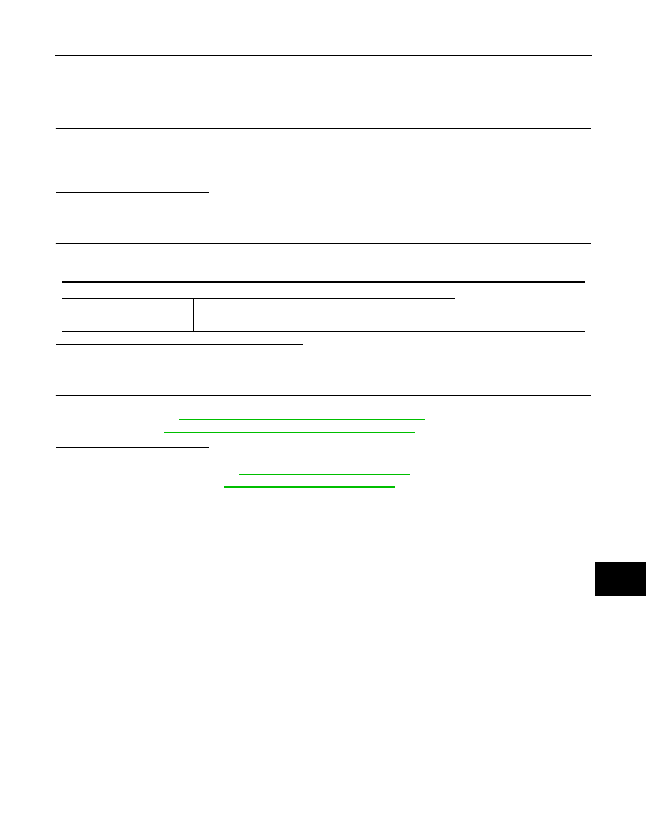
Check the resistance between the A/C auto amp. harness connector terminals.

Is the measurement value within the specification?

YES

>> GO TO 3.

NO

>> Repair the A/C auto amp. branch line.

3.

CHECK POWER SUPPLY AND GROUND CIRCUIT

Check the power supply and the ground circuit of the A/C auto amp. Refer to the following.
• Without 7 inch display: 

HAC-77, "A/C AUTO AMP. : Diagnosis Procedure"

• With 7 inch display: 

HAC-202, "A/C AUTO AMP. : Diagnosis Procedure"

Is the inspection result normal?

YES (Present error)>>Replace the A/C auto amp. Refer to the following.

• Without 7 inch display: 

VTL-25, "Removal and Installation"

• With 7 inch display: 

VTL-89, "Removal and Installation"

YES (Past error)>>Error was detected in the A/C auto amp. branch line.
NO

>> Repair the power supply and the ground circuit.

A/C auto amp. harness connector

Resistance (

)

Connector No.

Terminal No.

M50

1

2

Approx. 54 – 66

LAN-104

< DTC/CIRCUIT DIAGNOSIS >

[CAN SYSTEM (TYPE 3)]

M&A BRANCH LINE CIRCUIT

M&A BRANCH LINE CIRCUIT

Diagnosis Procedure

INFOID:0000000010092789

1.

CHECK CONNECTOR

1.

Turn the ignition switch OFF.

2.

Disconnect the battery cable from the negative terminal.

3.

Check the terminals and connectors of the combination meter for damage, bend and loose connection
(unit side and connector side).

Is the inspection result normal?

YES

>> GO TO 2.

NO

>> Repair the terminal and connector.

2.

CHECK HARNESS FOR OPEN CIRCUIT

1.

Disconnect the connector of combination meter.

2.

Check the resistance between the combination meter harness connector terminals.

Is the measurement value within the specification?

YES

>> GO TO 3.

NO

>> Repair the combination meter branch line.

3.

CHECK POWER SUPPLY AND GROUND CIRCUIT

Check the power supply and the ground circuit of the combination meter. Refer to 

MWI-44, "COMBINATION

METER : Diagnosis Procedure"

.

Is the inspection result normal?

YES (Present error)>>Replace the combination meter. Refer to 

MWI-105, "Removal and Installation"

.

YES (Past error)>>Error was detected in the combination meter branch line.
NO

>> Repair the power supply and the ground circuit.

Combination meter harness connector

Resistance (

)

Connector No.

Terminal No.

M34

21

22

Approx. 54 – 66

LAN

A-BAG BRANCH LINE CIRCUIT

LAN-105

< DTC/CIRCUIT DIAGNOSIS >

[CAN SYSTEM (TYPE 3)]

C

D

E

F

G

H

I

J

K

L

B

A

O

P

N

A-BAG BRANCH LINE CIRCUIT

Diagnosis Procedure

INFOID:0000000010092790

WARNING:

• Before servicing, turn ignition switch OFF, disconnect battery negative terminal, and wait 3 minutes

or more. (To discharge backup capacitor.)

• Never use unspecified tester or other measuring device.

1.

CHECK CONNECTOR

Check the terminals and connectors of the air bag diagnosis sensor unit for damage, bend and loose connec-
tion (unit side and connector side).

Is the inspection result normal?

YES

>> GO TO 2.

NO

>> Replace the terminal and connector.

2.

CHECK AIR BAG DIAGNOSIS SENSOR UNIT

Check the air bag diagnosis sensor unit. Refer to the following.
• For USA and CANADA: 

SRC-4, "Work Flow"

• For MEXICO: 

SRC-84, "Work Flow"

Is the inspection result normal?

YES

>> Replace the main harness.

NO

>> Replace parts whose air bag system has a malfunction.

LAN-106

< DTC/CIRCUIT DIAGNOSIS >

[CAN SYSTEM (TYPE 3)]

BCM BRANCH LINE CIRCUIT

BCM BRANCH LINE CIRCUIT

Diagnosis Procedure

INFOID:0000000010092791

1.

CHECK CONNECTOR

1.

Turn the ignition switch OFF.

2.

Disconnect the battery cable from the negative terminal.

3.

Check the terminals and connectors of the BCM for damage, bend and loose connection (unit side and
connector side).

Is the inspection result normal?

YES

>> GO TO 2.

NO

>> Repair the terminal and connector.

2.

CHECK HARNESS FOR OPEN CIRCUIT

1.

Disconnect the connector of BCM.

2.

Check the resistance between the BCM harness connector terminals.

Is the measurement value within the specification?

YES

>> GO TO 3.

NO

>> Repair the BCM branch line.

3.

CHECK POWER SUPPLY AND GROUND CIRCUIT

Check the power supply and the ground circuit of the BCM. Refer to 

BCS-46, "Diagnosis Procedure"

.

Is the inspection result normal?

YES (Present error)>>Replace the BCM. Refer to 

BCS-98, "Removal and Installation"

.

YES (Past error)>>Error was detected in the BCM branch line.
NO

>> Repair the power supply and the ground circuit.

BCM harness connector

Resistance (

)

Connector No.

Terminal No.

M122

91

90

Approx. 54 – 66


содержание   ..  946  947  948  949   ..