содержание .. 863 864 865 866 ..
Nissan Murano. Manual - part 865
HAC-234
< SYMPTOM DIAGNOSIS >
[WITH 7 INCH DISPLAY]
INSUFFICIENT COOLING
1.
Using CONSULT, perform “HVAC TEST” “ACTIVE TEST” of HVAC to check each output device. Refer to
NOTE:
Perform the ACTIVE TEST after starting the engine because the compressor is operated.
2.
Refer to the table and check the outlet, inlet, air flow temperature, blower motor control signal, magnet
clutch operation, and air mix ratio. Visually check each operating condition, by listening for noise, touching
air outlets with a hand, etc.
NOTE:
Perform the inspection of each output device after starting the engine because the compressor is operated.
Does it operate normally?
YES
>> GO TO 7.
Test item
MODE 1
MODE 2
MODE 3
MODE 4
MODE 5
MODE 6
MODE 7
Mode door position
VENT1
VENT2
B/L1
B/L2
FOOT
D/F
DEF
Intake door position
REC
REC
20%FRE
20%FRE
FRE
FRE
FRE
Air mix door position
(driver & passenger
side)
FULL COLD
FULL HOT
FULL COLD
FULL HOT
FULL HOT
FULL HOT
FULL HOT
Blower motor duty ratio
35%
35%
61%
61%
81%
81%
35%
Compressor (Magnet
clutch)
ON
ON
ON
ON
OFF
OFF
ON
Upper ventilator door
OPEN
SHUT
OPEN
SHUT
SHUT
SHUT
SHUT
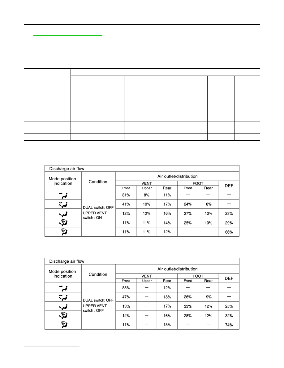
JPIIA0509GB
JPIIA0510GB