содержание .. 825 826 827 828 ..
Nissan Murano. Manual - part 827
HAC-82
< ECU DIAGNOSIS INFORMATION >
[WITHOUT 7 INCH DISPLAY]
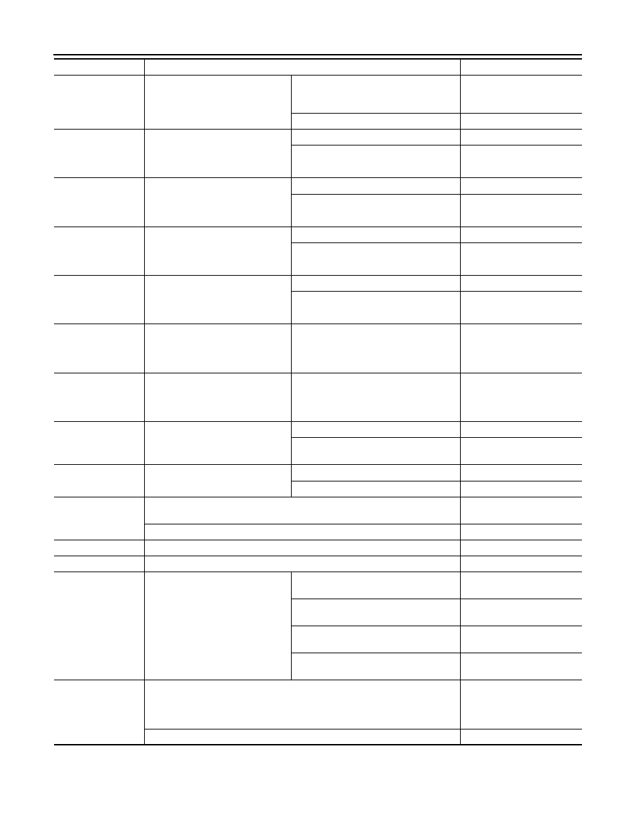
ECM
PURG VOL C/V
• Engine: After warming up
• Selector lever: P or N position
• Air conditioner switch: OFF
• No load
Idle
(Accelerator pedal: Not depressed even
slightly, after engine starting.)
0%
2,000 rpm
—
INT/V TIM (B1)
• Engine: After warming up
• Selector lever: P or N position
• Air conditioner switch: OFF
• No load
Idle
−
5 - 5
°
CA
2,000 rpm
Approx. 0 - 30
°
CA
INT/V TIM (B2)
• Engine: After warming up
• Selector lever: P or N position
• Air conditioner switch: OFF
• No load
Idle
−
5 - 5
°
CA
2,000 rpm
Approx. 0 - 30
°
CA
INT/V SOL (B1)
• Engine: After warming up
• Selector lever: P or N position
• Air conditioner switch: OFF
• No load
Idle
0 - 2%
2,000 rpm
Approx. 0 - 50%
INT/V SOL (B2)
• Engine: After warming up
• Selector lever: P or N position
• Air conditioner switch: OFF
• No load
Idle
0 - 2%
2,000 rpm
Approx. 0 - 50%
VIAS S/V-1
• Engine: After warming up
• Selector lever: P or N position
• Air conditioner switch: OFF
• No load
When revving engine up to 5,000 rpm
quickly
OFF
→
ON
→
OFF
VIAS S/V-2
• Engine: After warming up
• Selector lever: P or N position
• Air conditioner switch: OFF
• No load
When revving engine up to 5,000 rpm
quickly
OFF
→
ON
→
OFF
AIR COND RLY
• Engine: After warming up, idle the
engine
Air conditioner switch: OFF
OFF
Air conditioner switch: ON
(Compressor operates)
ON
ENGINE MOUNT
• Engine: After warming up
Idle (With vehicle stopped)
IDLE
Except above conditions
TRVL
FUEL PUMP RLY
• For 1 second after turning ignition switch: ON
• Engine running or cranking
ON
• Except above
OFF
VENT CONT/V
• Ignition switch: ON
OFF
THRTL RELAY
• Ignition switch: ON
ON
COOLING FAN
• Engine: After warming up, idle the
engine
• Air conditioner switch: OFF
Engine coolant temperature: 97
°
C
(206
°
F) or less
OFF
Engine coolant temperature: Between
98
°
C (208
°
F) and 99
°
C (210
°
F)
LOW
Engine coolant temperature: Between
100
°
C (212
°
F) and 104
°
C (219
°
F)
MID
Engine coolant temperature: 105
°
C
(221
°
F) or more
HI
HO2S2 HTR (B1)
• Engine speed: Below 3,600 rpm after the following conditions are met.
- Engine: After warming up
- Keeping the engine speed between 3,500 and 4,000 rpm for 1 minute and at
idle for 1 minute under no load
ON
• Engine speed: Above 3,600 rpm
OFF
Monitor Item
Condition
Values/Status