содержание .. 813 814 815 816 ..
Nissan Murano. Manual - part 815
HAC-34
< SYSTEM DESCRIPTION >
[WITHOUT 7 INCH DISPLAY]
INTAKE DOOR CONTROL SYSTEM
INTAKE DOOR CONTROL SYSTEM
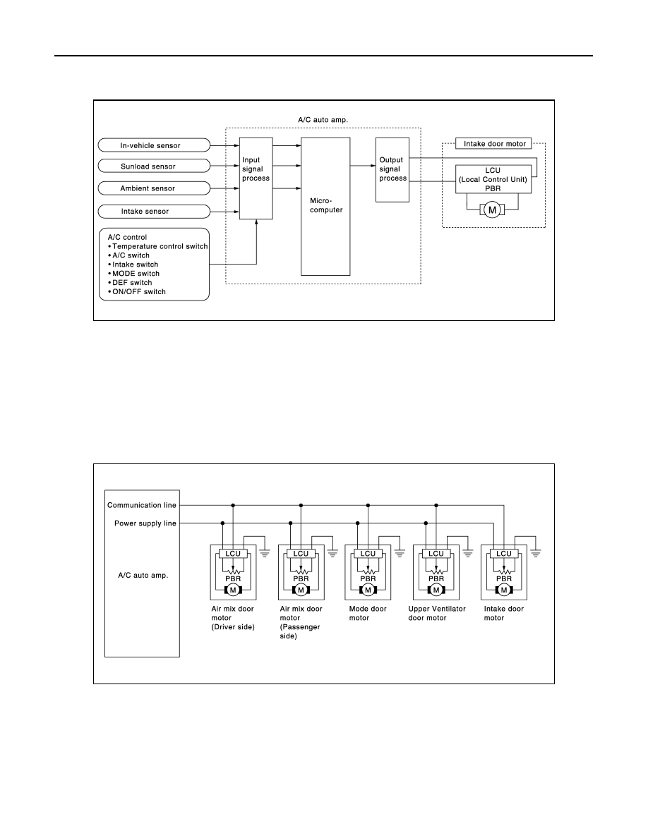
System Diagram
INFOID:0000000009722043
System Description
INFOID:0000000009722044
The intake doors are automatically controlled by the temperature setting, ambient temperature, in-vehicle tem-
perature, intake temperature, amount of sunload and ON/OFF operation of the compressor.
SYSTEM OPERATION
The intake door control judges intake door position based on the ambient temperature, the intake air tempera-
ture and the in-vehicle temperature. When in shifting mode position D/F, if the DEF or ON/OFF switches are
pressed, or when the A/C switch is OFF, the A/C auto amp. sets the intake door to the FRE position.
Door Motor Circuit
Intake Door Control Specification
JMIIA0493GB
JPIIA0495GB