содержание .. 796 797 798 799 ..
Nissan Murano. Manual - part 798
HA-28
< PERIODIC MAINTENANCE >
REFRIGERATION SYSTEM
REFRIGERATION SYSTEM
Inspection
INFOID:0000000009718631
1.
CHECK BLOWER MOTOR OPERATION
Check blower motor operation. Refer to
HAC-70, "Component Function Check"
(WITHOUT 7 INCH DIS-
PLAY) or
HAC-196, "Component Function Check"
(WITH 7 INCH DISPLAY).
Is the inspection result normal?
YES
>> GO TO 2.
NO
>> Repair or replace the parts according to the inspection results.
2.
CHECK COMPRESSOR OPERATION
Check compressor operation. Refer to
HAC-74, "Component Function Check"
(WITHOUT 7 INCH DISPLAY)
or
HAC-200, "Component Function Check"
(WITH 7 INCH DISPLAY).
Is the inspection result normal?
YES
>> GO TO 3.
NO
>> Repair or replace the parts according to the inspection results.
3.
CHECK REFRIGERANT CYCLE PRESSURE
Connect recovery/recycling recharging equipment to the vehicle and perform the diagnosis with the gauge
pressure. Refer to
HA-8, "Trouble Diagnosis For Unusual Pressure"
Is the inspection result normal?
YES
>> Perform the performance test. Refer to
.
NO
>> Repair or replace the parts according to the inspection results.
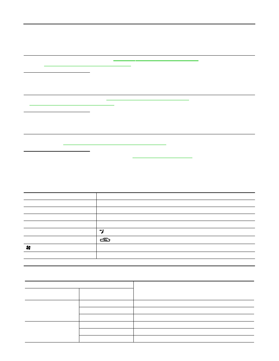
Performance Chart
INFOID:0000000009718632
TEST CONDITION
Testing must be performed under the following conditions:
TEST READING
Recirculating-to-discharge Air Temperature Table
Vehicle condition
Indoors or in the shade (in a well-ventilated place)
Doors
Closed
Door windows
Open
Hood
Open
Temperature control dial/switch
Full cold
Mode switch
(Ventilation) set
Intake switch
(Recirculation) set
Fan (blower) speed
Maximum speed set
Engine speed
Idle speed
Operate the air conditioning system for 10 minutes before taking measurements.
Inside air (Recirculating air) at blower assembly inlet
Discharge air temperature at center ventilator
°
C (
°
F)
Relative humidity
%
Air temperature
°
C (
°
F)
50 - 60
20 (68)
5.9 - 7.9 (43 - 46)
25 (77)
9.6 - 12.1 (49 - 54)
30 (86)
12.8 - 15.9 (55 - 61)
60 - 70
20 (68)
7.9 - 10.0 (46 - 50)
25 (77)
12.1 - 14.6 (54 - 58)
30 (86)
15.9 - 18.9 (61 - 66)