содержание .. 771 772 773 774 ..
Nissan Murano. Manual - part 773
FSU-14
< REMOVAL AND INSTALLATION >
FRONT STABILIZER
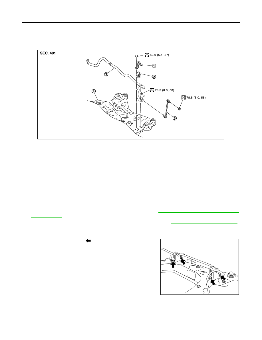
FRONT STABILIZER
Exploded View
INFOID:0000000009721411
Removal and Installation
INFOID:0000000009721412
REMOVAL
1.
Remove tires power tool.
2.
Remove front exhaust tube. Refer to
3.
Remove rear propeller shaft from transfer. (AWD models) Refer to
.
4.
Remove lock plate. Refer to
BR-22, "FRONT : Exploded View"
.
5.
Remove wheel sensor harness from strut assembly. Refer to
BRC-123, "FRONT WHEEL SENSOR :
.
6.
Disconnect power steering solenoid valve harness connector. Refer to
ST-48, "Removal and Installation"
7.
Remove steering outer socket from steering knuckle. Refer to
.
8.
Remove stabilizer connecting rod.
9.
Remove mounting bolts (
) of stabilizer clamp, and then
remove stabilizer clamp and stabilizer bushing from front sus-
pension member.
10. Remove stabilizer bar.
INSTALLATION
Note the following, and install in the reverse order of removal.
1.
Stabilizer clamp
2.
Stabilizer bushing
3.
Stabilizer bar
4.
Front suspension member
5.
Stabilizer connecting rod
Refer to
for symbols in the figure.
JPEIA0092GB
WEIA0182E