содержание .. 759 760 761 762 ..
Nissan Murano. Manual - part 761
FRONT WHEEL HUB AND KNUCKLE
FAX-39
< REMOVAL AND INSTALLATION >
[AWD]
C
E
F
G
H
I
J
K
L
M
A
B
FAX
N
O
P
10. Remove drive shaft from wheel hub and bearing assembly, suspend the drive shaft with suitable wire.
11. Temporarily tighten strut assembly and steering knuckle.
12. Remove wheel hub and bearing assembly, and then remove splash guard.
13. Remove steering outer socket from steering knuckle. Refer to
.
14. Remove steering knuckle from transverse link.
15. Remove steering knuckle from steering knuckle.
INSTALLATION
Note the following, and install in the reverse order of the removal.
• Clean the matching surface of wheel hub lock nut and wheel hub and bearing assembly.
CAUTION:
Never apply lubricating oil to these matching surface.
• Clean the matching surface of drive shaft and wheel hub and bearing assembly.
CAUTION:
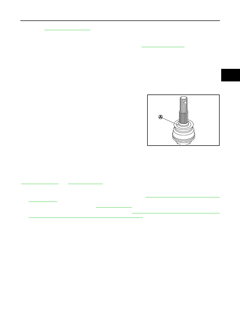
Apply paste [service parts (440037S000)] to cover entire flat
surface (A) of joint sub-assembly of drive shaft.
• Never use a power tool to tighten the wheel hub lock nut.
• Perform the final tightening of each of parts under unladen condi-
tions, which were removed when removing wheel hub and bearing
assembly and axle housing.
• Never reuse cotter pin.
Inspection
INFOID:0000000009717920
INSPECTION AFTER REMOVAL
Check components for deformation, cracks, and other damage. Replace if necessary.
Ball Joint Inspection
Check boots of transverse link and steering outer socket ball joint for breakage, axial play, and torque. Refer to
INSPECTION AFTER INSTALLATION
1.
Check wheel sensor harness for proper connection. Refer to
BRC-123, "FRONT WHEEL SENSOR :
.
2.
Check the wheel alignment. Refer to
.
3.
Adjust neutral position of steering angle sensor. Refer to
BRC-9, "ADJUSTMENT OF STEERING ANGLE
SENSOR NEUTRAL POSITION : Special Repair Requirement"
.
Amount paste
: 1.0 – 3.0 g (0.04 – 0.10 oz)
JPDIG0122ZZ