содержание .. 635 636 637 638 ..
Nissan Murano. Manual - part 637
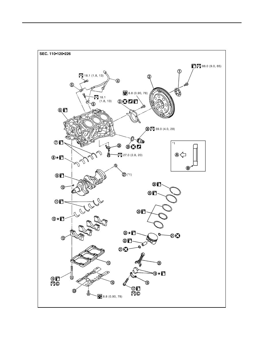
EM-122
< UNIT DISASSEMBLY AND ASSEMBLY >
CYLINDER BLOCK
CYLINDER BLOCK
Exploded View
INFOID:0000000009718006
1.
Reinforcement plate
2.
Drive plate
3.
Rear oil seal retainer
4.
Sub harness
5.
Knock sensor
6.
Cylinder block
7.
Thrust bearing (upper)
8.
Main bearing (upper)
9.
Crankshaft
JPBIA1673GB