Nissan Murano. Manual - part 504


  Главная      Nissan     Nissan Murano (2014 year) - Service Manual


поиск по сайту            


содержание   ..  502  503  504  505   ..


Nissan Murano. Manual - part 504


EC-126

< SYSTEM DESCRIPTION >

[VQ35DE]

DIAGNOSIS SYSTEM (ECM)

PERMANENT DTC SET TIMING

The setting timing of permanent DTC is stored in control module with the lighting of MIL when a DTC is con-
firmed.

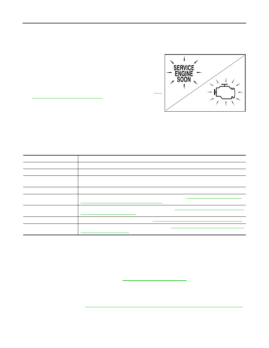
DIAGNOSIS DESCRIPTION : Malfunction Indicator Lamp (MIL)

INFOID:0000000009719873

When emission-related ECU detects a malfunction in the emission
control systems components and/or the powertrain control compo-
nents (which affect vehicle emissions), it turns on/blinks MIL to
inform the driver that a malfunction has been detected.
1.

The MIL illuminates when ignition switch is turned ON (engine is
not running).
NOTE:
Check the MIL circuit if MIL does not illuminate. Refer to 

EC-

458, "Component Function Check"

.

2.

When the engine is started, the MIL should go off.
NOTE:
If MIL continues to illuminate/blink, perform self-diagnoses and
inspect/repair accordingly because an emission-related ECU has detected a malfunction in the emission
control systems components and/or the powertrain control components (which affect vehicle emissions).

On Board Diagnosis Function

INFOID:0000000009719874

ON BOARD DIAGNOSIS ITEM

The on board diagnostic system has the following functions.

BULB CHECK MODE

Description

This function allows damage inspection in the MIL bulb (blown, open circuit, etc.).

Operation Procedure

1.

Turn ignition switch ON.

2.

The MIL on the instrument panel should stay ON.
If it remains OFF, check MIL circuit. Refer to 

EC-458, "Diagnosis Procedure"

.

SRT STATUS MODE

Description

This function allows to read if ECM has completed the self-diagnoses of major emission control systems and
components. For SRT, refer to 

EC-124, "DIAGNOSIS DESCRIPTION : System Readiness Test (SRT) Code"

.

Operation Procedure

1.

Turn ignition switch ON and wait 20 seconds.

2.

SRT status is indicated as shown blow.
• ECM continues to illuminate MIL if all SRT codes are set.

JSBIA1315ZZ

Diagnostic test mode

Function

Bulb check

MIL can be checked. 

SRT status

ECM can read if SRT codes are set.

Malfunction warning

If ECM detects a malfunction, it illuminates or blinks MIL to inform the driver that a malfunction has 
been detected.

Self-diagnostic results

DTCs or 1st trip DTCs stored in ECM can be read.

Accelerator pedal released po-
sition learning

ECM can learn the accelerator pedal released position. Refer to 

EC-19, "ACCELERATOR PEDAL 

RELEASED POSITION LEARNING : Description"

.

Throttle valve closed position 
learning

ECM can learn the throttle valve closed position. Refer to 

EC-19, "THROTTLE VALVE CLOSED PO-

SITION LEARNING : Description"

.

Idle air volume learning

ECM can learn the idle air volume. Refer to 

EC-20, "IDLE AIR VOLUME LEARNING : Description"

.

Mixture ratio self-learning value 
clear

Mixture ratio self-learning value can be erased. Refer to 

EC-21, "MIXTURE RATIO SELF-LEARNING 

VALUE CLEAR : Description"

.

DIAGNOSIS SYSTEM (ECM)

EC-127

< SYSTEM DESCRIPTION >

[VQ35DE]

C

D

E

F

G

H

I

J

K

L

M

A

EC

N

P

O

• ECM blinks MIL for about 10 seconds if all SRT codes are not set.

MALFUNCTION WARNING MODE

Description

In this function ECM turns on or blinks MIL when it detects a malfunction in the emission control system com-
ponents and/or the powertrain control components (which affect vehicle emissions) to inform the driver that a
malfunction has been detected.

Operation Procedure

1.

Turn ignition switch ON.

2.

Check that MIL illuminates.
If it remains OFF, check MIL circuit. Refer to 

EC-458, "Diagnosis Procedure"

.

3.

Start engine and let it idle.
• For two trip detection logic diagnoses, ECM turns on MIL when it detects the same malfunction twice in

the two consecutive driving cycles.

• For 1st trip detection logic diagnoses, ECM turns on MIL when it detects a malfunction in one driving

cycle.

• ECM blinks MIL when it detects a malfunction that may damage the three way catalyst (misfire).

SELF-DIAGNOSTIC RESULTS MODE

Description

This function allows to indicate DTCs or 1st trip DTCs stored in ECM according to the number of times MIL is
blinking.

How to Set Self-diagnostic Results Mode

NOTE:
• It is better to count the time accurately with a clock.
• It is impossible to switch the diagnostic mode when an accelerator pedal position sensor circuit has a mal-

function.

• After ignition switch is turned off, ECM is always released from the “self-diagnostic results” mode.
1.

Confirm that accelerator pedal is fully released, turn ignition switch ON and wait 3 seconds.

2.

Repeat the following procedure quickly five times within 5 seconds.
• Fully depress the accelerator pedal.
• Fully release the accelerator pedal.

3.

Wait 7 seconds, fully depress the accelerator pedal and keep it depressed for approx. 10 seconds until the
MIL starts blinking.
NOTE:
Do not release the accelerator pedal for 10 seconds if MIL starts blinking during this period. This blinking
is displaying SRT status and is continued for another 10 seconds.

4.

Fully release the accelerator pedal.
ECM has entered to “Self-diagnostic results” mode.

JMBIA1515GB

EC-128

< SYSTEM DESCRIPTION >

[VQ35DE]

DIAGNOSIS SYSTEM (ECM)

NOTE:
Wait until the same DTC (or 1st trip DTC) appears to completely confirm all DTCs.

How to Read Self-diagnostic Results

The DTC and 1st trip DTC are indicated by the number of blinks of the MIL as shown below.
The DTC and 1st trip DTC are displayed at the same time. If the MIL does not illuminate in diagnostic test
mode I (Malfunction warning), all displayed items are 1st trip DTCs. If only one code is displayed when the MIL
illuminates in “malfunction warning” mode, it is a DTC; if two or more codes are displayed, they may be either
DTCs or 1st trip DTCs. DTC No. is same as that of 1st trip DTC. These unidentified codes can be identified by
using the CONSULT or GST. A DTC will be used as an example for how to read a code.

A particular trouble code can be identified by the number of four-digit numeral flashes per the following.

The length of time the 1,000th-digit numeral flashes on and off is 1.2 seconds consisting of an ON (0.6-sec-
onds) - OFF (0.6-seconds) cycle.
The 100th-digit numeral and lower digit numerals consist of a 0.3-seconds ON and 0.3-seconds OFF cycle.
A change from one digit numeral to another occurs at an interval of 1.0-second OFF. In other words, the later
numeral appears on the display 1.3 seconds after the former numeral has disappeared.
A change from one trouble code to another occurs at an interval of 1.8-seconds OFF.

PBIB0092E

PBIB3005E

Number

0

1

2

3

4

5

6

7

8

9

A

B

C

D

E

F

Flashes

10

1

2

3

4

5

6

7

8

9

11

12

13

14

15

16

DIAGNOSIS SYSTEM (ECM)

EC-129

< SYSTEM DESCRIPTION >

[VQ35DE]

C

D

E

F

G

H

I

J

K

L

M

A

EC

N

P

O

In this way, all the detected malfunctions are classified by their DTC numbers. The DTC 0000 refers to no mal-
function. Refer to 

EC-507, "DTC Index"

.

How to Erase Self-diagnostic Results

By performing this procedure, ECM memory is erased and the following diagnostic information is erased as
well.
• Diagnostic trouble codes
• 1st trip diagnostic trouble codes
• Freeze frame data
• 1st trip freeze frame data
• System readiness test (SRT) codes
• Test values
NOTE:
Also, if a battery terminal is disconnected, ECM memory is erased and the diagnostic information as listed
above is erased. (The amount of time required for erasing may vary from a few seconds to several hours.)

1.

Turn ignition switch OFF and wait at least 10 seconds.

2.

Turn ignition switch ON.

3.

Turn ignition switch OFF and wait at least 10 seconds.

4.

Turn ignition switch ON.

5.

Set ECM in “self-diagnostic results” mode.

6.

The diagnostic information has been erased from the backup memory in the ECM.
Fully depress the accelerator pedal and keep it depressed for more than 10 seconds.

7.

Fully release the accelerator pedal, and confirm the DTC 0000 is displayed.

CONSULT Function

INFOID:0000000009719875

FUNCTION

*: The following emission-related diagnostic information is cleared when the ECM memory is erased.

• Diagnostic trouble codes

• 1st trip diagnostic trouble codes

• Freeze frame data

• 1st trip freeze frame data

• System readiness test (SRT) codes

• Test  values

SELF DIAGNOSTIC RESULT MODE

Self Diagnostic Item

Regarding items of DTC and 1st trip DTC, refer to 

EC-507, "DTC Index"

.

How to Read DTC and 1st Trip DTC

DTCs and 1st trip DTCs related to the malfunction are displayed in “self-diag results”.
• When ECM detects a 1st trip DTC, 1t” is displayed for “TIME”.
• When ECM has detected a current DTC, “0” is displayed for “TIME”.
• If “TIME” is neither “0” nor “1t”, the DTC occurred in the past and ECM shows the number of times the vehi-

cle has been driven since the last detection of the DTC.

Diagnostic test mode

Function

Self Diagnostic Result

Self-diagnostic results such as 1st trip DTC, DTCs and 1st trip freeze frame data or freeze frame data 
can be read and erased quickly.*

Data Monitor

Input/Output data in the ECM can be read.

Work support

This mode enables a technician to adjust some devices faster and more accurately by following the in-
dications on the CONSULT unit.

Active Test

Diagnostic Test Mode in which CONSULT drives some actuators apart from the ECMs and also shifts 
some parameters in a specified range.

ECU Identification

ECM part number can be read.

DTC Work Support

The status of system monitoring tests and the self-diagnosis status/results can be confirmed.


содержание   ..  502  503  504  505   ..