Nissan Murano. Manual - part 445


  Главная      Nissan     Nissan Murano (2014 year) - Service Manual


поиск по сайту            


содержание   ..  443  444  445  446   ..


Nissan Murano. Manual - part 445


U1000 CAN COMM CIRCUIT

DLN-19

< DTC/CIRCUIT DIAGNOSIS >

[TRANSFER: TY20A]

C

E

F

G

H

I

J

K

L

M

A

B

DLN

N

O

P

U1000 CAN COMM CIRCUIT

Description

INFOID:0000000009718094

CAN (Controller Area Network) is a serial communication line for real time application. It is an on-vehicle mul-
tiplex communication line with high data communication speed and excellent error detection ability. Many elec-
tronic control units are equipped onto a vehicle, and each control unit shares information and links with other
control units during operation (not independent). In CAN communication, control units are connected with 2
communication lines (CAN-H line, CAN-L line) allowing a high rate of information transmission with less wiring.
Each control unit communicate data but selectively reads required data only.

DTC Logic

INFOID:0000000009718095

DTC DETECTION LOGIC

DTC CONFIRMATION PROCEDURE

1.

DTC REPRODUCTION PROCEDURE

With CONSULT

1.

Turn the ignition switch OFF to ON.

2.

Perform self-diagnosis for “ALL MODE AWD/4WD”.

Is DTC “U1000” detected?

YES

>> Proceed to diagnosis procedure. Refer to 

DLN-19, "Diagnosis Procedure"

.

NO

>> INSPECTION END

Diagnosis Procedure

INFOID:0000000009718096

Proceed to 

LAN-18, "Trouble Diagnosis Flow Chart"
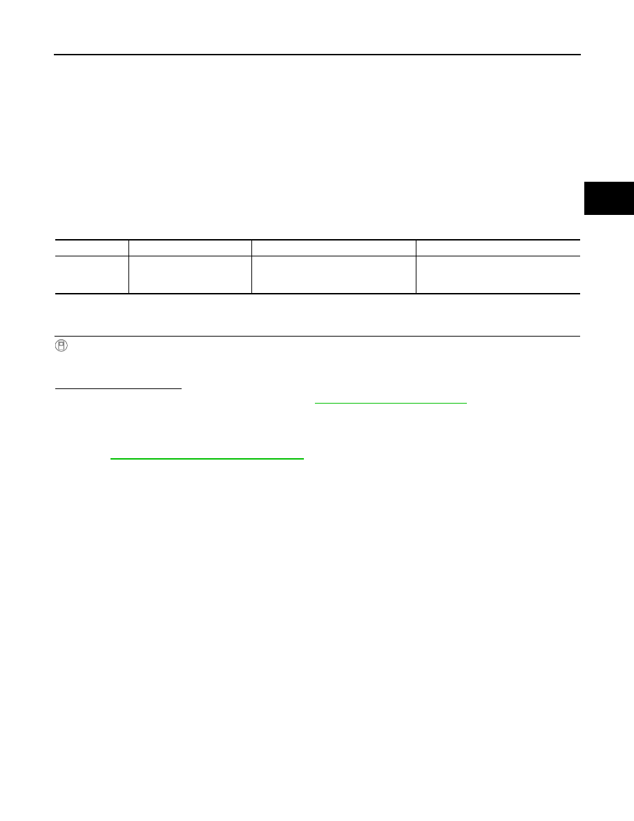
.

DTC

Display item

Malfunction detected condition

Possible cause

U1000

CAN COMM CIRCUIT

AWD control unit is not transmitting/re-
ceiving CAN communication signal for 2 
seconds or more.

• CAN communication error
• Malfunction of AWD control unit

DLN-20

< DTC/CIRCUIT DIAGNOSIS >

[TRANSFER: TY20A]

U1010 CONTROL UNIT (CAN)

U1010 CONTROL UNIT (CAN)

Description

INFOID:0000000009718097

CAN (Controller Area Network) is a serial communication line for real time application. It is an on-vehicle mul-
tiplex communication line with high data communication speed and excellent error detection ability. Many elec-
tronic control units are equipped onto a vehicle, and each control unit shares information and links with other
control units during operation (not independent). In CAN communication, control units are connected with 2
communication lines (CAN-H line, CAN-L line) allowing a high rate of information transmission with less wiring.
Each control unit communicate data but selectively reads required data only.

DTC Logic

INFOID:0000000009718098

DTC DETECTION LOGIC

DTC CONFIRMATION PROCEDURE

1.

DTC REPRODUCTION PROCEDURE

With CONSULT

1.

Turn the ignition switch OFF to ON.

2.

Perform self-diagnosis for “ALL MODE AWD/4WD”.

Is DTC “U1010” detected?

YES 

>> Proceed to diagnosis procedure. Refer to 

DLN-20, "Diagnosis Procedure"

.

NO

>> INSPECTION END

Diagnosis Procedure

INFOID:0000000009718099

1.

CHECK AWD CONTROL UNIT

Check AWD control unit harness connector for disconnection and deformation.

Is the inspection result normal? 

YES

>> Replace AWD control unit. Refer to 

DLN-53, "Exploded View"

.

NO

>> Repair or replace error-detected parts.

DTC

Display item

Malfunction detected condition

Possible cause

U1010

CONTROL UNIT (CAN)

Detecting error during the initial diagno-
sis of CAN controller of AWD control 
unit.

Malfunction of AWD control unit

POWER SUPPLY AND GROUND CIRCUIT

DLN-21

< DTC/CIRCUIT DIAGNOSIS >

[TRANSFER: TY20A]

C

E

F

G

H

I

J

K

L

M

A

B

DLN

N

O

P

POWER SUPPLY AND GROUND CIRCUIT

Description

INFOID:0000000009718100

Supplies power to AWD control unit.

Diagnosis Procedure

INFOID:0000000009718101

1.

CHECK AWD CONTROL UNIT POWER SUPPLY (1)

1.

Turn the ignition switch OFF.

2.

Disconnect AWD control unit harness connector.

3.

Check the voltage between AWD control unit harness connector and ground.

4.

Turn the ignition switch ON.

CAUTION:

Never start the engine.

5.

Check the voltage between AWD control unit harness connector and ground.

Is the inspection result normal?

YES

>> GO TO 3.

NO

>> GO TO 2.

2.

CHECK AWD CONTROL UNIT POWER SUPPLY (2)

1.

Turn the ignition switch OFF.

2.

Check the 10A fuse (#45).

3.

Disconnect IPDM E/R harness connector.

4.

Check the continuity between AWD control unit harness connector and IPDM E/R harness connector.

5.

Check the continuity between AWD control unit harness connector and the ground.

Is the inspection result normal?

YES

>> Perform the trouble diagnosis for ignition power supply circuit. Refer to 

PG-47, "Wiring Diagram -

IGNITION POWER SUPPLY -"

.

NO

>> Repair or replace error-detected parts.

3.

CHECK AWD SOLENOID POWER SUPPLY (1)

1.

Turn the ignition switch OFF.

2.

Disconnect AWD solenoid harness connector.

3.

Check the voltage between AWD control unit harness connector and ground.

AWD control unit

Voltage (Approx.)

Connector

Terminal

M69

7

Ground

0 V

AWD control unit

Voltage 

Connector

Terminal

M69

7

Ground

Battery voltage

AWD control unit

IPDM E/R

Continuity

Connector

Terminal

Connector

Terminal

M69

7

E10

26

Existed

AWD control unit

Continuity

Connector

Terminal

M69

7

Ground

Not existed

DLN-22

< DTC/CIRCUIT DIAGNOSIS >

[TRANSFER: TY20A]

POWER SUPPLY AND GROUND CIRCUIT

4.

Turn the ignition switch ON.

CAUTION:

Never start the engine.

5.

Check the voltage between AWD control unit harness connector and ground.

Is the inspection result normal?

YES

>> GO TO 5.

NO

>> GO TO 4.

4.

CHECK AWD SOLENOID POWER SUPPLY (2)

1.

Turn the ignition switch OFF.

2.

Check the 10A fuse (#36).

Is the inspection result normal?

YES

>> Perform the trouble diagnosis for power supply circuit. Refer to 

PG-6, "Wiring Diagram - BAT-

TERY POWER SUPPLY -"

.

NO

>> Repair or replace error-detected parts.

5.

CHECK AWD CONTROL UNIT GROUND

1.

Turn the ignition switch OFF.

2.

Check the continuity between AWD control unit harness connector and ground.

Is the inspection result normal?

YES

>> INSPECTION END

NO

>> Repair or replace error-detected parts.

AWD control unit

Voltage

Connector

Terminal

M69

9

Ground

Battery voltage

AWD control unit

Voltage

Connector

Terminal

M69

9

Ground

Battery voltage

AWD control unit

Continuity

Connector

Terminal

M69

10

Ground

Existed

11


содержание   ..  443  444  445  446   ..