Nissan Murano. Manual - part 380


  Главная      Nissan     Nissan Murano (2014 year) - Service Manual


поиск по сайту            


содержание   ..  378  379  380  381   ..


Nissan Murano. Manual - part 380


KEY SLOT ILLUMINATION

DLK-131

< DTC/CIRCUIT DIAGNOSIS >

[WITH INTELLIGENT KEY SYSTEM]

C

D

E

F

G

H

I

J

L

M

A

B

DLK

N

O

P

KEY SLOT ILLUMINATION

Description

INFOID:0000000009719046

Blinks when Intelligent Key insertion is required.

Component Function Check

INFOID:0000000009719047

1.

CHECK FUNCTION

Check key slot illumination (“KEY SLOT ILLUMI”) Active Test mode.

Is the inspection result normal?

YES

>> Key slot function is OK.

NO

>> Refer to 

DLK-131, "Diagnosis Procedure"

.

Diagnosis Procedure

INFOID:0000000009719048

1.

CHECK FUSE

1.

Turn ignition switch OFF.

2.

Check 10 A fuse, [No.9, located in fuse block (J/B)].

Is fuse fusing?

YES

>> Replace the blown fuse after repairing the affected circuit if a fuse is blown.

NO

>> GO TO 2.

2.

CHECK KEY SLOT ILLUMINATION OUTPUT SIGNAL 

Check voltage between key slot connector and ground.

Is the inspection result normal?

YES

>> GO TO 3.

NO

>> GO TO 4.

3.

CHECK KEY SLOT CIRCUIT

1.

Disconnect BCM and key slot connector.

2.

Check continuity between BCM harness connector and key slot harness connector.

3.

Check continuity between BCM harness connector and ground.

Is the inspection result normal?

YES

>> Replace BCM. Refer to 

BCS-98, "Removal and Installation"

.

NO

>> Repair or replace harness.

4.

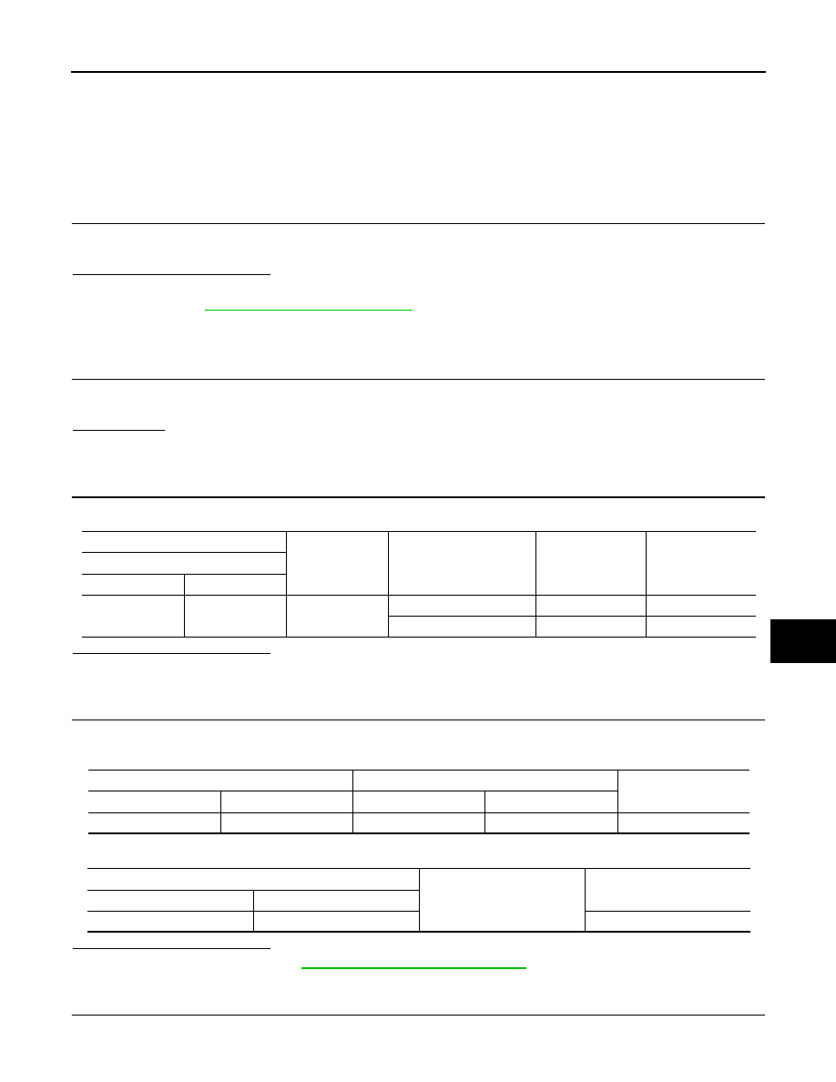
CHECK KEY SLOT POWER SUPPLY CIRCUIT

1.

Disconnect key slot connector.

(+)

(–)

Condition

Key slot

illumination

Voltage (V)         

 (Approx.)

Key slot

Connector

Terminal

M99

6

Ground

Intelligent Key inserted

OFF

Battery voltage

Intelligent Key removed

ON

0

BCM

Key slot

Continuity

Connector

Terminal

Connector

Terminal

M122

92

M99

6

Existed

BCM

Ground

Continuity 

Connector

Terminal

M122

92

Not existed

DLK-132

< DTC/CIRCUIT DIAGNOSIS >

[WITH INTELLIGENT KEY SYSTEM]

KEY SLOT ILLUMINATION

2.

Check voltage between key slot harness connector and ground.

Is the inspection result normal?

YES

>> GO TO 5.

NO

>> Repair or replace key slot power supply circuit.

5.

CHECK KEY SLOT GROUND CIRCUIT

Check continuity between key slot harness connector and ground.

Is the inspection result normal?

YES

>> GO TO 6.

NO

>> Repair or replace key slot ground circuit.

6.

CHECK KEY SLOT 

Refer to 

DLK-132, "Component Inspection"

.

Is the inspection result normal?

YES

>> GO TO 7.

NO

>> Replace key slot. Refer to 

DLK-364, "Removal and Installation"

.

7.

CHECK INTERMITTENT INCIDENT 

Refer to 

GI-44, "Intermittent Incident"

.

>> INSPECTION END

Component Inspection

INFOID:0000000009719049

1.

CHECK KEY SLOT ILLUMINATION

1.

Turn ignition switch OFF.

2.

Disconnect key slot connector.

3.

Connect battery power supply to key slot terminals 5 and 6, and check the operation.

Is the inspection result normal?

YES

>> INSPECTION END

NO

>> Replace key slot. Refer to 

DLK-364, "Removal and Installation"

.

(+)

(–)

Voltage (V)

(Approx.)

Key slot

Connector

Terminal

M99

5

Ground

Battery voltage

Key slot

Ground

Continuity

Connector

Terminal

M99

7

Existed

5 (BAT+) - 6 (BAT-)

: Key slot illuminates

HORN FUNCTION

DLK-133

< DTC/CIRCUIT DIAGNOSIS >

[WITH INTELLIGENT KEY SYSTEM]

C

D

E

F

G

H

I

J

L

M

A

B

DLK

N

O

P

HORN FUNCTION

Description

INFOID:0000000009719050

Perform answer-back for each operation with horn.

Component Function Check

INFOID:0000000009719051

1.

CHECK FUNCTION

1.

Select “HORN” in “ACTIVE TEST” mode with CONSULT.

2.

Check the horn (high/low) operation.

Is the operation normal?

YES

>> Horn function is OK.

NO

>> Go to 

DLK-133, "Diagnosis Procedure"

.

Diagnosis Procedure

INFOID:0000000009719052

1.

CHECK HORN FUNCTION

Check horn function with horn switch

Do the horns sound?

YES

>> GO TO 2.

NO

>> Go to 

HRN-2, "Wiring Diagram - HORN -"

.

2.

CHECK HORN RELAY POWER SUPPLY

1.

Turn ignition switch ON.

2.

Perform “ACTIVE TEST” (“HORN”) with CONSULT-Ill.

3.

Check voltage between horn relay harness connector and ground.

Is the inspection result normal?

YES

>> GO TO 4.

NO

>> GO TO 3.

3.

CHECK HORN RELAY CIRCUIT

1.

Turn ignition switch OFF.

2.

Disconnect IPDM E/R connector and horn relay connector.

3.

Check continuity between IPDM E/R harness connector and horn relay harness connector.

4.

Check continuity between driver seat control unit harness connector and ground.

Is the inspection result normal?

Test item

Description

HORN

ON

Horn relay

ON (for 20 ms)

Horn relay

Ground

Test item

Voltage (V)

(Approx.)

Connector

Terminal

E5

1

HORN

ON

Battery voltage 

 0 


Battery voltage

Other than above

Battery voltage

IPDM E/R

Horn relay

Continuity

Connector

Terminal

Connector

Terminal

E11

44

E5

1

Existed

IPDM E/R

Ground

Continuity 

Connector

Terminal

E11

44

Not existed

DLK-134

< DTC/CIRCUIT DIAGNOSIS >

[WITH INTELLIGENT KEY SYSTEM]

HORN FUNCTION

YES

>> Replace IPDM E/R. Refer to 

PCS-37, "Removal and Installation"

.

NO

>> Repair or replace harness.

4.

CHECK INTERMITTENT INCIDENT

Refer to 

GI-44, "Intermittent Incident"

.

Is the inspection result normal?

>> INSPECTION END


содержание   ..  378  379  380  381   ..