Nissan Murano. Manual - part 371


  Главная      Nissan     Nissan Murano (2014 year) - Service Manual


поиск по сайту            


содержание   ..  369  370  371  372   ..


Nissan Murano. Manual - part 371


POWER SUPPLY AND GROUND CIRCUIT

DLK-95

< DTC/CIRCUIT DIAGNOSIS >

[WITH INTELLIGENT KEY SYSTEM]

C

D

E

F

G

H

I

J

L

M

A

B

DLK

N

O

P

POWER SUPPLY AND GROUND CIRCUIT

BCM (BODY CONTROL MODULE)

BCM (BODY CONTROL MODULE) : Diagnosis Procedure

INFOID:0000000009718976

1.

CHECK FUSE AND FUSIBLE LINK

Check that the following fuse and fusible link are not blown.

Is the fuse fusing?

YES

>> Replace the blown fuse or fusible link after repairing the affected circuit if a fuse or fusible link is

blown.

NO

>> GO TO 2.

2.

CHECK POWER SUPPLY CIRCUIT

1.

Turn ignition switch OFF.

2.

Disconnect BCM connectors.

3.

Check voltage between BCM harness connector and ground.

Is the measurement value normal?

YES

>> GO TO 3.

NO

>> Repair harness or connector.

3.

CHECK GROUND CIRCUIT

Check continuity between BCM harness connector and ground.

Does continuity exist?

YES

>> INSPECTION END

NO

>> Repair harness or connector.

AUTOMATIC BACK DOOR CONTROL UNIT

AUTOMATIC BACK DOOR CONTROL UNIT : Diagnosis Procedure

INFOID:0000000009718977

1.

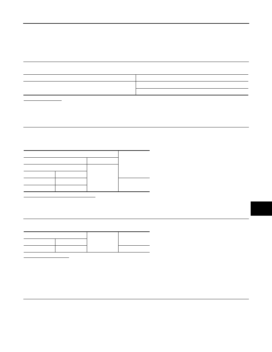
CHECK FUSE, FUSIBLE LINK AND CIRCUIT BREAKER

Check that the following fuse, fusible link and circuit breaker are not fusing.

Signal name

Fuse and fusible link No.

Battery power supply

L

10

Terminals

Voltage

(Approx.)

(+)

(

)

BCM

Ground

Connector

Terminal

M118

1

Battery voltage

M119

11

BCM

Ground

Continuity

Connector

Terminal

M119

13

Existed

DLK-96

< DTC/CIRCUIT DIAGNOSIS >

[WITH INTELLIGENT KEY SYSTEM]

POWER SUPPLY AND GROUND CIRCUIT

Is the fuse fusing?

YES

>> Replace the blown fuse or fusible link after repairing the affected circuit if a fuse or fusible link is

blown.

NO

>> GO TO 2.

2.

CHECK POWER SUPPLY CIRCUIT

1.

Turn ignition switch OFF.

2.

Disconnect automatic back door control unit connector.

3.

Check voltage between automatic back door control unit harness connector and ground.

Is the measurement value normal?

YES

>> GO TO 3.

NO

>> Repair or replace harness.

3.

CHECK GROUND CIRCUIT

Check continuity between automatic back door control unit harness connector and ground.

Does continuity exist?

YES

>> INSPECTION END

NO

>> Repair or replace harness.

Fuse and fusible link No.

Signal name

J

Battery power supply

Circuit breaker

6

3

Ignition power supply

(+)

(

)

Condition

Voltage

(Approx.)

Automatic back door control unit

Connector

Terminal

B8

9

Ground

Ignition switch: ON

Battery voltage

10

B7

28

Automatic back door control unit

Ground

Continuity

Connector

Terminal

B7

34

Existed

DOOR SWITCH

DLK-97

< DTC/CIRCUIT DIAGNOSIS >

[WITH INTELLIGENT KEY SYSTEM]

C

D

E

F

G

H

I

J

L

M

A

B

DLK

N

O

P

DOOR SWITCH

WITH AUTOMATIC BACK DOOR

WITH AUTOMATIC BACK DOOR : Description

INFOID:0000000009718978

Detects door open/close condition.

WITH AUTOMATIC BACK DOOR : Component Function Check

INFOID:0000000009718979

1.

CHECK FUNCTION

With CONSULT

Check door switches (“DOOR SW-DR”, “DOOR SW-AS”, “DOOR SW-RL”, “DOOR SW-RR” and “DOOR SW-
BK”) in Data Monitor” mode with CONSULT.

Is the inspection result normal?

YES

>> Door switch is OK.

NO

>> Refer to 

DLK-97, "WITH AUTOMATIC BACK DOOR : Diagnosis Procedure"

.

WITH AUTOMATIC BACK DOOR : Diagnosis Procedure

INFOID:0000000009718980

1.

CHECK DOOR SWITCH INPUT SIGNAL

1.

Turn ignition switch OFF.

2.

Disconnect malfunctioning door switch connector.

3.

Check signal between malfunctioning door switch harness connector and ground with oscilloscope.

Is the inspection result normal?

YES-1 >> Back door: GO TO 3.
YES-2 >> Other doors: GO TO 4.
NO

>> GO TO 2.

2.

CHECK DOOR SWITCH CIRCUIT 

1.

Disconnect BCM connector.

2.

Check continuity between BCM harness connector and door switch harness connector.

Monitor item

Condition

DOOR SW-DR

CLOSE 

 OPEN: OFF 

 ON

DOOR SW-AS

DOOR SW-RL

DOOR SW-RR

DOOR SW-BK

(+)

(–)

Voltage (V)

(Approx.)

Door switch

Connector

Terminal

Driver side

B32

3

Ground

Passenger side

B233

Rear LH

B31

Rear RH

B232

Back door

D179

7

JPMIA0011GB

DLK-98

< DTC/CIRCUIT DIAGNOSIS >

[WITH INTELLIGENT KEY SYSTEM]

DOOR SWITCH

3.

Check continuity between BCM harness connector and ground.

Is the inspection result normal?

YES

>> Replace BCM. Refer to 

BCS-98, "Removal and Installation"

.

NO

>> Repair or replace harness.

3.

CHECK BACK DOOR SWITCH GROUND CIRCUIT

Check continuity between back door lock assembly (back door switch) harness connector and ground.

Is the inspection result normal?

YES

>> GO TO 4.

NO

>> Repair or replace harness.

4.

CHECK DOOR SWITCH 

Refer to 

DLK-98, "WITH AUTOMATIC BACK DOOR : Component Inspection"

.

Is the inspection result normal?

YES

>> GO TO 5.

NO

>>

Replace malfunctioning door switch.

• Door switch: Refer to 

DLK-358, "Removal and Installation"

.

• Back door lock assembly (back door switch): Refer to 

DLK-351, "DOOR LOCK : Removal and

Installation"

.

5.

CHECK INTERMITTENT INCIDENT

Refer to 

GI-44, "Intermittent Incident"

.

>> INSPECTION END 

WITH AUTOMATIC BACK DOOR : Component Inspection

INFOID:0000000009718981

1.

CHECK DOOR SWITCH

1.

Turn ignition switch OFF.

2.

Disconnect door switch connector.

3.

Check door switch terminals.

BCM

Door switch

Continuity 

Connector

Terminal

Connector

Terminal

M123

150

B32

2

Existed

124

B233

M121

69

B31

68

B232

66

D179

7

BCM

Ground

Continuity 

Connector

Terminal

M123

B32

Not existed

B233

M121

B31

B232

D179

Back door lock assembly (back door switch)

Ground

Continuity

Connector

Terminal

D179

8

Existed


содержание   ..  369  370  371  372   ..